ESD protection component and method for manufacturing ESD protection component

a technology of protection components and protection components, applied in the direction of resistors, multiple fixed capacitor combinations, structural fixed capacitor combinations, etc., to achieve the effect of improving esd absorption capability

Active Publication Date: 2015-02-05
TDK CORPARATION
View PDF3 Cites 10 Cited by
  • Summary
  • Abstract
  • Description
  • Claims
  • Application Information

AI Technical Summary

Benefits of technology

[0027]Incidentally, the Inventors conducted elaborate research on the ESD protection components capable of achieving improvement in ESD absorption capability and discovered the new fact as described below. The value of DC resistance of the coil connected in parallel to the ESD suppressor configured including the first discharge electrode and the second discharge electrode affects the ESD absorption capability. Specifically, as the value of DC resistance of the coil increases, an effect of suppressing the peak voltage becomes lower, resulting in degradation of the peak voltage. Furthermore, when the value of DC resistance of the coil exceeds 21Ω, this degradation of the peak voltage is accelerated. Namely, it was found that the tendency of change of the ESD absorption capability against the value of DC resistance of the coil switched at a certain variation point.
[0028]As a consequence of this, the Inventors came to have not only such a finding that the ESD absorption capability could be improved more with decreasing value of DC resistance of the coil, but also such a finding that the ESD absorption capability could be effectively improved by division at the certain variation point of not more than 21Ω.

Problems solved by technology

However, if the discharge inducing portion and the cavity portion were introduced to the ESD protection component having the configuration wherein the coil and the ESD suppressor are arranged in the element body, the problem as described below could arise.

Method used


Image

  • ESD protection component and method for manufacturing ESD protection component
  • ESD protection component and method for manufacturing ESD protection component
  • ESD protection component and method for manufacturing ESD protection component

Examples


first embodiment

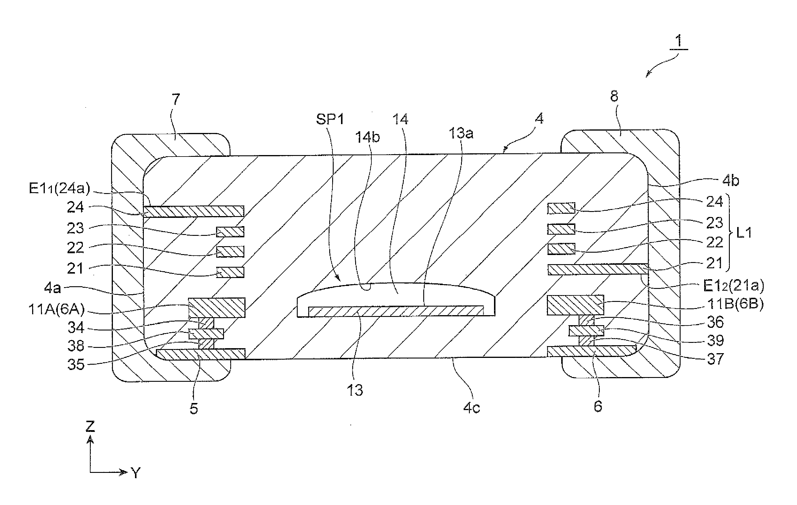
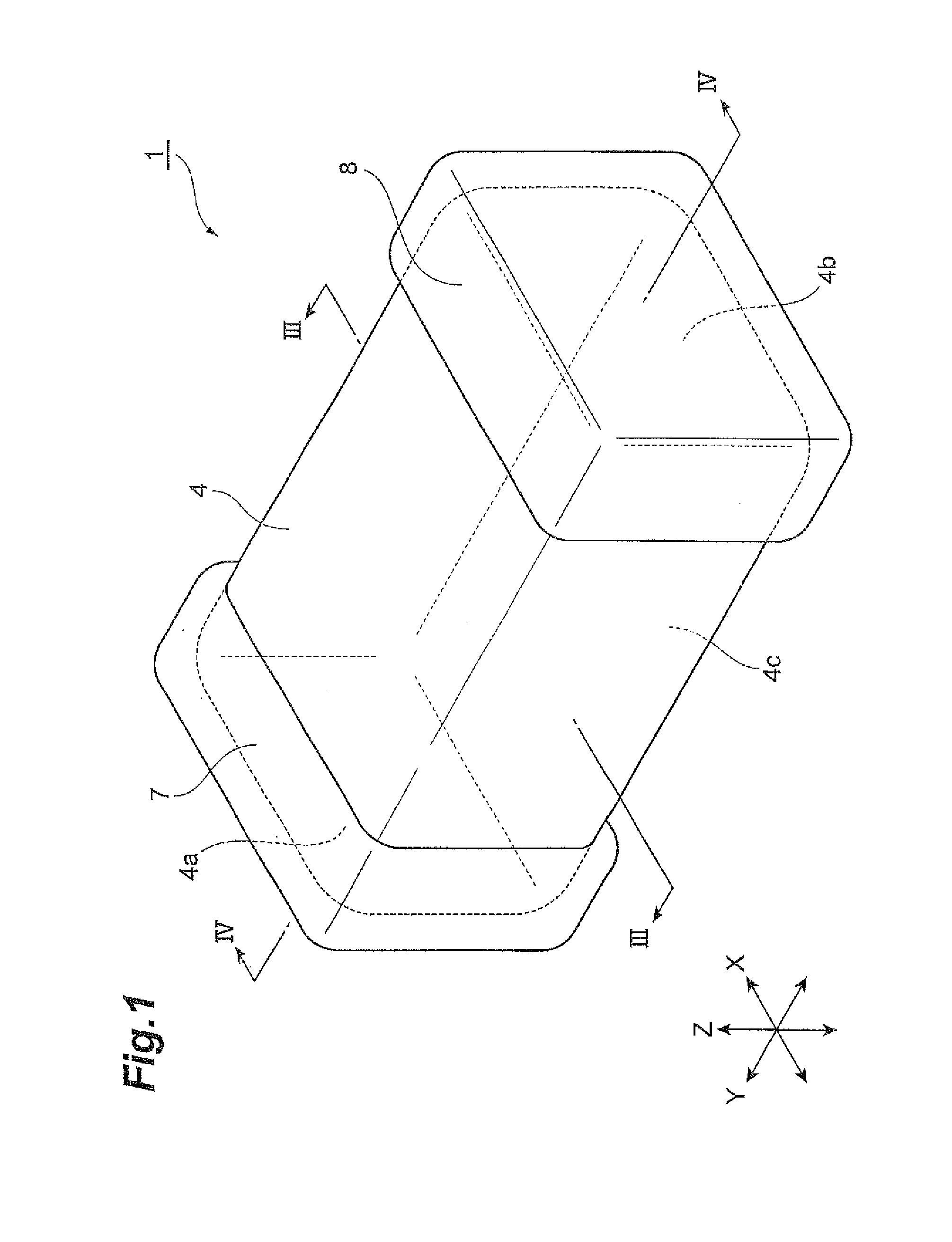
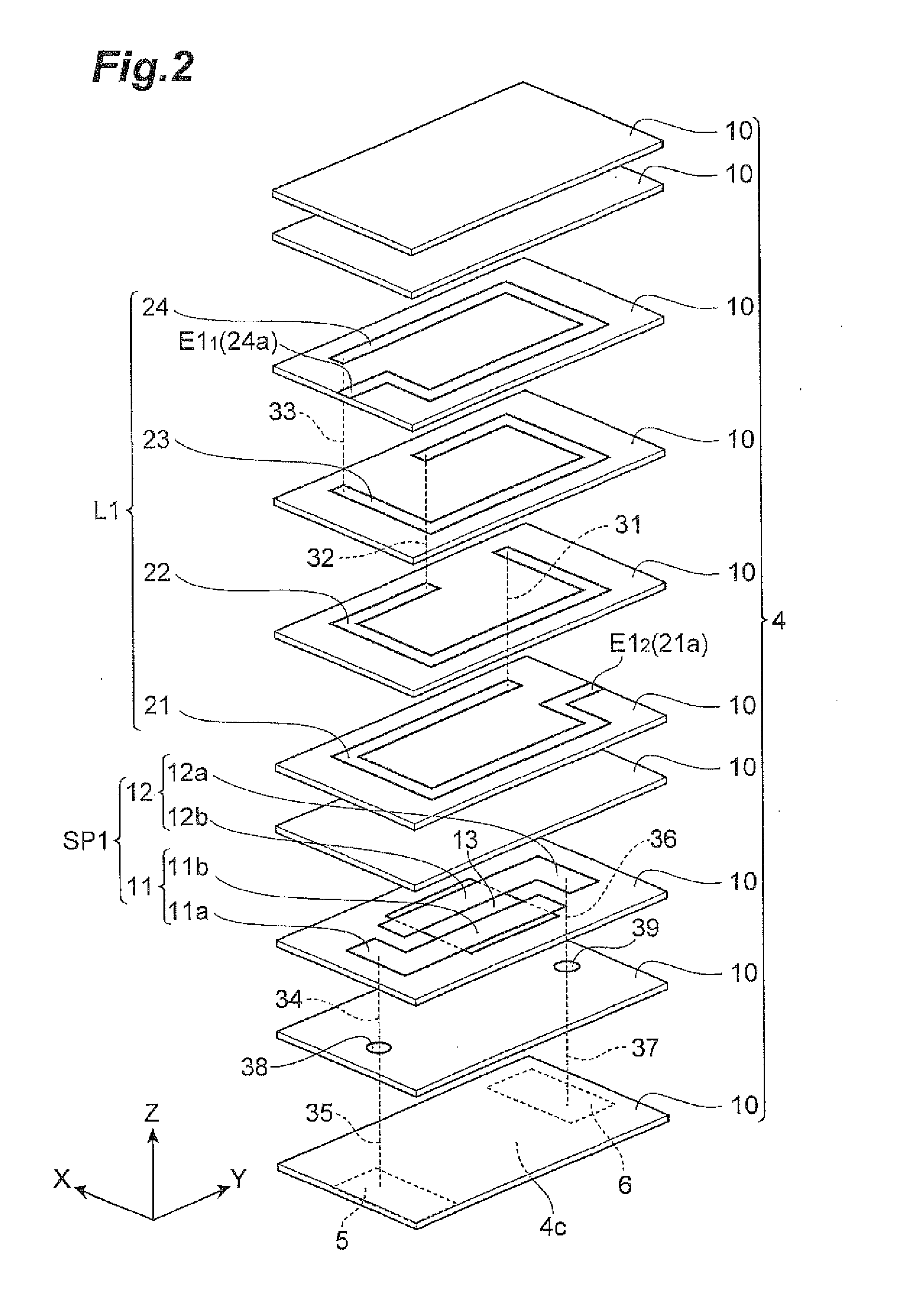
[0053]First, a configuration of an ESD protection component 1 according to the first embodiment will be described with reference to FIGS. 1 to 4. FIG. 1 is a perspective view showing the ESD protection component according to the present embodiment. FIG. 2 is an exploded perspective view showing a configuration of an element body. FIG. 3 is a drawing showing a cross-sectional configuration along the line III-III shown in FIG. 1. FIG. 4 is a drawing showing a cross-sectional configuration along the line IV-IV shown in FIG. 1.

[0054]The ESD protection component 1 is an electronic component that is to be mounted on a circuit board of an electronic device to protect the electronic device from ESD. As shown in FIGS. 1 to 4, the ESD protection component 1 is provided with an element body 4 of a nearly rectangular parallelepiped shape, an external electrode 5, an external electrode 6, an external electrode 7, and an external electrode 8 arranged on the exterior surface of the element body 4,...

second embodiment

[0093]Next, a configuration of an ESD protection component 2 according to the second embodiment will be described with reference to FIGS. 6 to 10. FIG. 6 is a perspective view showing the ESD protection component according to the second embodiment. FIG. 7 is an exploded perspective view showing a configuration of an element body. FIG. 8 is a drawing showing a cross-sectional configuration including a first ESD suppressor and a third ESD suppressor, of the ESD protection component according to the second embodiment. FIG. 9 is a drawing showing a cross-sectional configuration including a second ESD suppressor and a fourth ESD suppressor, of the ESD protection component according to the second embodiment. FIG. 10 is a drawing showing a cross-sectional configuration including the first ESD suppressor and the fourth ESD suppressor, of the ESD protection component according to the second embodiment.

[0094]The ESD protection component 2, as shown in FIGS. 6 to 10, is provided with the eleme...

third embodiment

[0133]Next, a configuration of an ESD protection component 3 according to the third embodiment will be described with reference to FIGS. 6 and 11 to 13. FIG. 11 is an exploded perspective view showing a configuration of an element body which the ESD protection component according to the third embodiment has. FIG. 12 is a drawing showing a cross-sectional configuration including a first ESD suppressor and a second ESD suppressor, of the ESD protection component according to the third embodiment. FIG. 13 is a drawing showing a cross-sectional configuration including a third ESD suppressor and a fourth ESD suppressor, of the ESD protection component according to the third embodiment. FIG. 14 is a drawing showing a cross-sectional configuration including the first ESD suppressor and the third ESD suppressor, of the ESD protection component according to the third embodiment.

[0134]The ESD protection component 3 is provided with the element body 4, and the external electrode 41, the extern...


PUM


Abstract

An ESD suppressor is configured including first and second discharge electrodes arranged as separated from each other, and a discharge inducing portion kept in contact with the first and second discharge electrodes so as to connect mutually opposed portions of the first and second discharge electrodes to each other. The discharge inducing portion contains metal particles. The first and second discharge electrodes are located on the coil side with respect to the discharge inducing portion when viewed in a stack direction of a plurality of insulator layers. An element body has a cavity portion located so as to cover the whole of the discharge inducing portion when viewed in the stack direction from the coil side. The cavity portion is in contact with the mutually opposed portions of the first and second discharge electrodes and with the discharge inducing portion.

Description

BACKGROUND OF THE INVENTION[0001]1. Field of the Invention[0002]The present invention relates to an ESD (electrostatic discharge) protection component and a method for manufacturing the EST protection component.[0003]2. Related Background Art[0004]There is a known ESD protection component provided with an element body in which a plurality of insulator layers are stacked, a coil constructed by connecting a plurality of internal conductors to each other and arranged in the element body, and an ESD suppressor arranged in the element body and configured including first and second discharge electrodes arranged as separated from each other (e.g., cf. Japanese Patent Application Laid-Open Publication No. 2003-123936 (which will be referred to hereinafter as Patent Literature 1)). There is another known ESD protection component provided with an ESD suppressor configured including first and second discharge electrodes arranged as separated from each other, and a discharge inducing portion ke...

Claims


Application Information

Patent Timeline
Patent Type & Authority Applications(United States)
IPC IPC(8): H02H9/04
CPCH02H9/044H01C13/02H01G4/38H01G4/40
Inventor UMEDA, HIDENOBUISHIKAWA, YUMAYOSHINO, MAKOTOHIGASHIDA, KEIGO
Owner TDK CORPARATION
Why Eureka
Try Eureka