Thermal interface material

a technology of thermal interface materials and materials, applied in the direction of lighting support devices, semiconductor/solid-state device details, lighting and heating apparatus, etc., can solve the problems of huge cost saving, achieve the effect of facilitating the increase of the thickness of the tim layer, facilitating the effect of improving the surface contact, and being convenient to us

Active Publication Date: 2015-02-05
KONINKLIJKE PHILIPS ELECTRONICS NV
View PDF5 Cites 11 Cited by
  • Summary
  • Abstract
  • Description
  • Claims
  • Application Information

AI Technical Summary

Benefits of technology

[0008]Additionally, the thermal interface according to the present invention further advantageously corrects for any surface curvature and roughness properties of the mating interfaces and will thus be much more robust in usage than other TIMs on the market today. The type of TIM as provided by the present invention therefore has the potential to replace a very large amount of TIMs used today in any system, apparatus or industry.
[0009]According to an embodiment of the TIM, the shrinkage material is provided in a predetermined oriented direction within the TIM. The oriented direction may be selected to be one of a single direction, multiple directions, a radial direction, a mesh, etc. The shrinkage material can further comprise oriented fibers or randomly oriented fibers within a selected plane etc. Preferably, the orientation of the shrinkage material is selected to further facilitate the increase of the thickness of the TIM layer, and to facilitate the effect of the improved surface contact at a location where heat dissipation is most needed.
[0010]According to an embodiment of the TIM, the oriented direction is selected within the TIM layer xy-plane, which is effective to further increase the shrinkage in the xy-direction of the TIM layer, thereby increasing the overall thickness of the TIM.
[0011]According to an embodiment of the TIM, the TIM layer is a multilayer TIM comprising alternate TIM sub layers and shrinkage material layers. The multilayer TIM is advantageous for instance in that it allows different TIM sub layers to have direct bonding or friction with at least one layer of shrinkage material, which effectively forces the TIM sub layers to adapt to the shrinkage material when it is activated, i.e. to retract material in the xy-dimension. Multilayer TIMs may be manufactured e.g. by means of laminating the different layers, which provides an easy and low cost way to assemble two different materials together to form one sheet material.
[0012]According to an embodiment of the TIM, the shrinkage material comprises monomers, and the activation of the shrinkage material causes the monomers to polymerize. As the monomers bond together during polymerization, the density of the shrinkage material increases which causes the volume of the shrinkage material to shrink. By mixing the monomers and the TIM material before polymerization, and selecting monomers that form polymer crosslink systems this may advantageously provide sufficient passage channels for the TIM material to guide heat through the TIM (in contrary to for instance applying a laminate heat shrinkage material which may cause an obstruction of the thermal path by a closed or open surface with less thermal conductive properties). The use of monomers / polymer netting, additionally enables other activation methods than heat, e.g. UV radiation or other chemical reactions.
[0013]According to an embodiment of the TIM, the shrinkage material is an expanded polymer matrix, and the activation of the shrinkage material causes the expanded polymer matrix to relax back to an un-expanded state. Here the shrinkage of the shrinkage material is thus expansion based. This is applicable for instance in that the polymer matrix may be prefabricated, and optionally expanded, in an external process before adding it to the TIM layer, or as part of a multilayer TIM before applying it between TIM sub layers. In addition this will allow cutting / shaping of the heat shrinkage material in specific shapes in order to influence the shrinkage behaviors in shrinkage directions and strength relatively to the TIM material. The cutting / shaping of the heat shrinkage material may include die cutting and / or perforation in repetitive or oriented patterns of a foil of heat shrinkage material.

Problems solved by technology

This strongly alleviates the system design with respect to the contact pressure and potentially provides a huge cost saving on both “bill of materials”, BOM, and assembly of the system, since now both interfaces only have to be kept in place and the TIM itself will take care of the physical contact.

Method used


Image

  • Thermal interface material
  • Thermal interface material
  • Thermal interface material

Examples


Embodiment Construction

[0026]Exemplifying embodiments of the thermal interface material, TIM, and its corresponding thermal interface application, methods on how to produce such TIM and thermal interface will now be described herein under.

[0027]The steps of the methods are described as a continuous sequence, however some of the steps may be performed in another order or some additional process step may be interleaved.

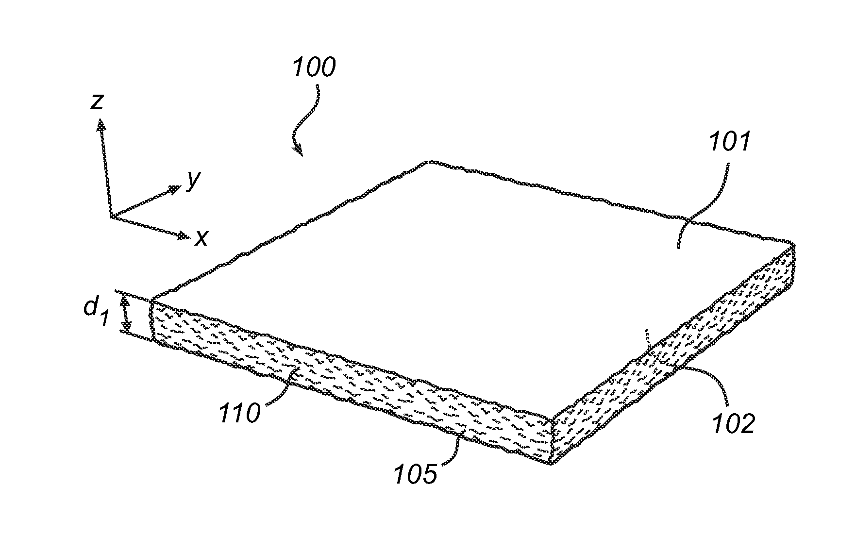
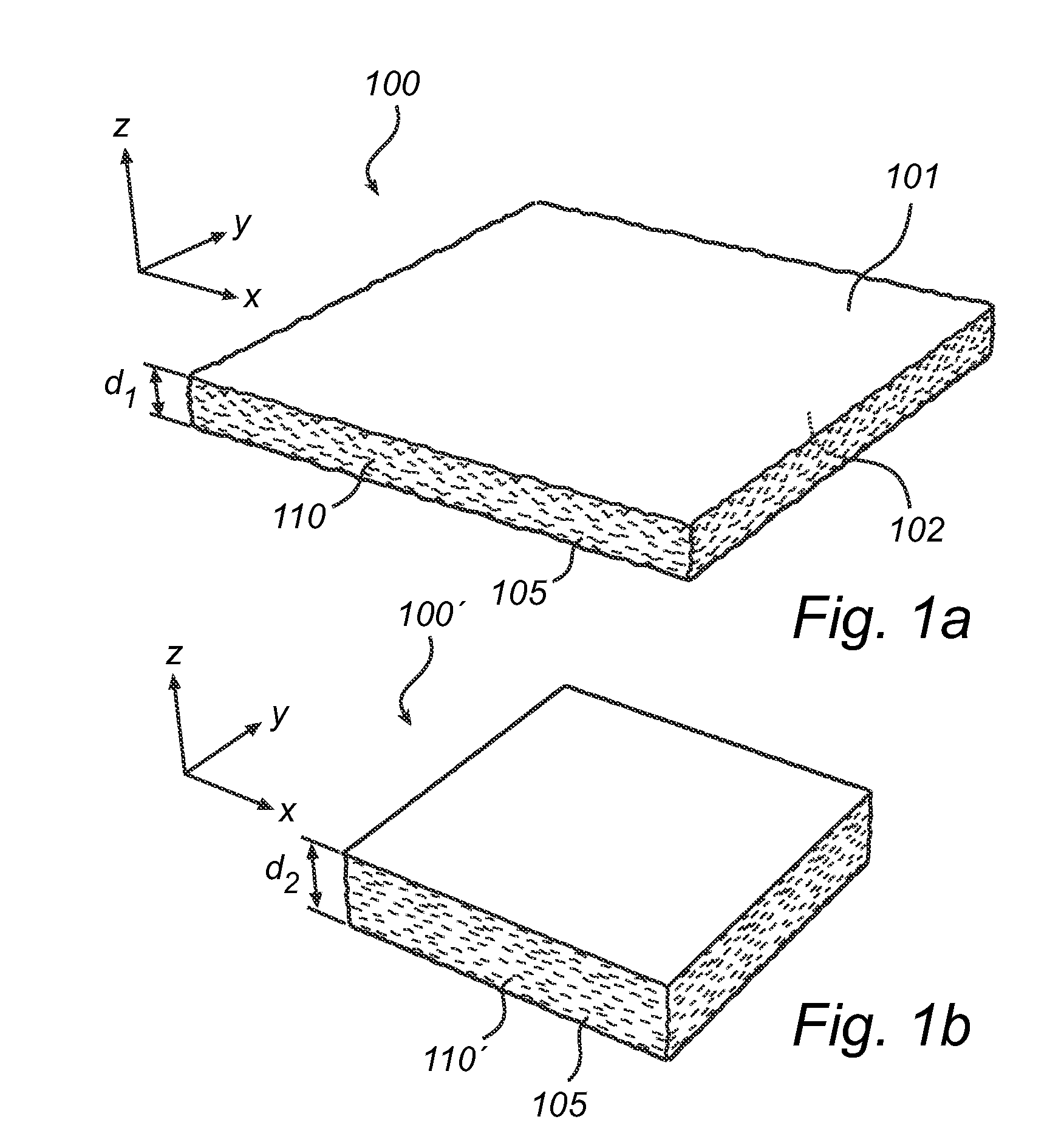
[0028]Referring now to FIG. 1a), which illustrates an embodiment100 of a TIM according to the present invention, the TIM 100 comprises a TIM-layer 105, i.e. a substantially flat material structure with and upper surface 101 and a lower surface 102 having a thickness d1 in the z-direction which is small compared to the extent of the physical dimensions of the layer in the xy-plane. A shrinkage material 110 is distributed within the TIM layer 105. The shrinkage material 110 is in this exemplifying embodiment heat sensitive polymer shrinkage fibers added to the TIM layer 105 material during manu...


PUM


Abstract

There is provided a thermal interface material, TIM, a thermal interface application comprising such a TIM, and corresponding methods for providing the material and the thermal interface. The TIM comprises a TIM layer in which an activable shrinkage material is distributed, such that upon activation of the shrinkage material the thickness of the TIM layer is increased. In the thermal interface application, where the TIM (400) is arranged between a heat generating component (20) and a heat conducting element (30), the increase in thickness of the TIM layer is utilized to increase the contact pressure on mating surfaces. The TIM is sandwiched between the heat generating component and the heat conducting element before the activation of the shrinkage material, and the distance (h) between the heat generating component and the heat conducting element is restricted such upon activation of the shrinkage material, the restricted maximum height (h) between the heat generating component and the heat conducting element in combination with the TIM increasing the thickness of the TIM layer, the contact pressure on the mating surfaces is increased.

Description

TECHNICAL FIELD[0001]The present invention relates to the field of thermal interface materials for thermal management of heat generating components, and more particularly to a thermal interface material according to the preamble of the independent claim.BACKGROUND OF THE INVENTION[0002]Thermal Interface Materials (TIMs) are thermally conductive materials typically designed to act as a thermal interface between a heat generating component, e.g. an electrical component, and a heat conducting element, e.g. a heat sink or a heat spreader, and to fill any voids or irregularities that may exist in the mating surfaces of the heat generating component and the heat conducting element. The latter increases the contact area between the heat generating component and the heat sink, thereby effectively reducing the thermal impedance between them and allowing for the efficient transfer of heat. To be effective, TIMs preferably have very low bulk thermal resistivity and a viscosity low enough to al...

Claims


Application Information

Patent Timeline
Patent Type & Authority Applications(United States)
IPC IPC(8): F28F3/00F21V29/00B29C55/12F28F21/00
CPCF28F3/00F28F21/00F21V29/22B29C55/12B29K2105/0002B29K2105/256B29K2995/0013B29L2009/00B29K2101/12F21Y2101/02H01L23/42H01L23/3737H01L2924/0002F21V29/70F21Y2115/10F21Y2101/00Y10T29/49366H01L2924/00F21V29/50
Inventor FLESKENS, BASDEN BOER, REINIER IMRE ANTON
Owner KONINKLIJKE PHILIPS ELECTRONICS NV
Why Eureka
Try Eureka