RFID devices using metamaterial antennas

a technology of metamaterials and antennas, applied in the field of radio frequency identification devices, can solve the problems of reducing performance, reducing and being susceptible to environments, so as to increase the bandwidth of the antenna system

Active Publication Date: 2015-02-12
HAND HELD PRODS
View PDF2 Cites 25 Cited by
  • Summary
  • Abstract
  • Description
  • Claims
  • Application Information

AI Technical Summary

Benefits of technology

[0003]There is provided an antenna system to increase bandwidth of antennas, such as metamaterial antennas in an RFID reader. Antenna systems may include multiple antenna elements, each of which may comprise different resonant frequencies. By allowing these multiple antenna elements to radiate at the same time or in an alternating fashion, the multiple resonant frequencies of the antenna signal increase the bandwidth of the antenna system.

Problems solved by technology

However, the antenna of the RFID reader may be susceptible to environments and may not have a broad bandwidth.
A small environmental factor (e.g., hand position on the terminal, etc.) may shift the band off targeted frequency, and greatly downgrade the performance.

Method used


Image

  • RFID devices using metamaterial antennas
  • RFID devices using metamaterial antennas
  • RFID devices using metamaterial antennas

Examples


first embodiment

Antenna to Generate Additional Resonance Frequencies

[0043]FIG. 4B illustrates an example of another MTM antenna 420 with increased bandwidth. FIG. 4B, in one embodiment, may include features similar to the MTM antenna of FIG. 4A, such as conductive feed line 416 coupled to conductive cell patch 402, via 404, dielectric substrate 408, and feed pad 414. Additionally, the MTM antenna of FIG. 4B may include a stripline portion 425 extending from a portion 430 of the conductive feed line 416. The length of the stripline portion 425 may be variable so that the resonant frequency generated by the addition of the stripline portion 425 is in addition to resonant frequencies in the circuit of FIG. 4A (i.e., without the stripline portion 425). By varying how long the stripline portion 425 is, a user can vary the insertion losses and bandwidth of an antenna, such as an RFID antenna.

[0044]FIG. 5 illustrates a graph of the insertion / return loss (S11) for the antenna of FIG. 4B. As illustrated, wi...

second embodiment

Antenna to Generate Additional Resonance Frequencies

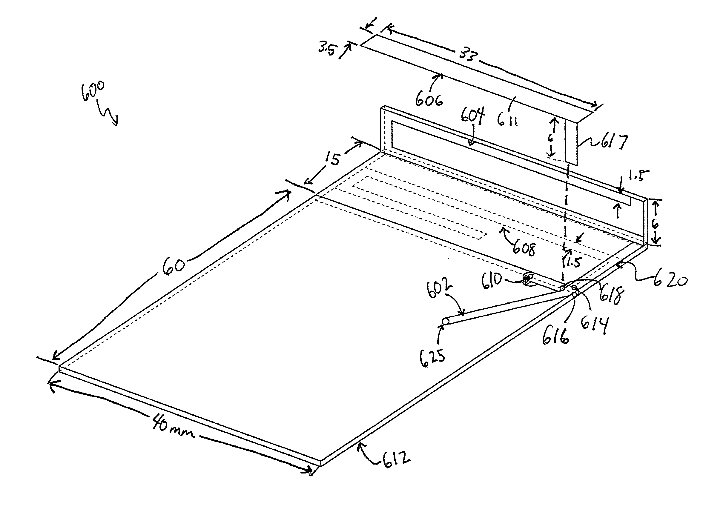
[0051]FIG. 6 illustrates an antenna system 600 generating multiple resonant frequencies according to one embodiment. Antenna system 600 may include a plurality of antennas. For example, the antenna system 600 of FIG. 6 includes three monopole antennas 604, 606, and 608. The monopole antennas 604, 606, and 608 are each fed at a common feed point 614. Monopole 604 extends along a plane that is perpendicular to the printed circuit board 615. Monopole 604 has a first length and is configured to generate a first resonant frequency for the antenna system 600. Monopole 604 is connected to feed point 614 via strip portion 620.

[0052]Monopole 606 extends along a plane that is parallel to but separate from a plane defined by the printed circuit board 615. Monopole 606 has a second length and is configured to generate a second resonant frequency for the antenna system 600. It is noted that monopole 606 has a first section 611 and a second port...


PUM


Abstract

An antenna system may include a first metamaterial antenna having a first resonant frequency and a second metamaterial antenna having a second resonant frequency. The first resonant frequency may be different from the second resonant frequency. A first feed point may be connected to the first metamaterial antenna, and a second feed point may be connected to the second metamaterial antenna. A signal may be applied to the first and second feed points so that the first and second metamaterial antennas radiates electromagnetic energy while the signal is being applied and so that the antenna system is configured to send or receive signals over both the first and second resonant frequency bands.

Description

FIELD OF THE INVENTION[0001]The invention is generally related to radio frequency identifier (RFID) devices and is specifically related to RFID tags and RFID reading devices using metamaterial antennas.BACKGROUND OF THE INVENTION[0002]RFID methods are widely used in a number of applications, including smart cards, item tracking in manufacturing and retail, etc. An RFID tag can be attached to an object, such as a retail item. An encoded information reading (EIR) terminal deployed at the cashier's desk can be equipped with an RFID reader to read and / or modify the memory of an RFID tag attached to a retail item. However, the antenna of the RFID reader may be susceptible to environments and may not have a broad bandwidth. A small environmental factor (e.g., hand position on the terminal, etc.) may shift the band off targeted frequency, and greatly downgrade the performance.SUMMARY OF THE INVENTION[0003]There is provided an antenna system to increase bandwidth of antennas, such as metama...

Claims


Application Information

Patent Timeline
Patent Type & Authority Applications(United States)
IPC IPC(8): G06K7/10H01Q21/30
CPCH01Q21/30G06K7/10356G06K7/10316G06K7/10346H01Q1/2216H01Q5/371H01Q9/42H01Q15/0086
Inventor QU, HUYUNUSSEIBEH, FOUADWANG, YNJIUN PAUL
Owner HAND HELD PRODS
Why Eureka
Try Eureka