Supercharge Your Innovation With Domain-Expert AI Agents!

Organic light emitting diode display

a light-emitting diode and organic technology, applied in the field can solve the problems of reducing efficiency, reducing light-emitting area, increasing deposition process and cost, etc., and achieve the effect of reducing luminance loss and increasing the luminance of organic light-emitting diodes

Inactive Publication Date: 2015-02-12
SAMSUNG DISPLAY CO LTD
View PDF16 Cites 32 Cited by
  • Summary
  • Abstract
  • Description
  • Claims
  • Application Information

AI Technical Summary

Benefits of technology

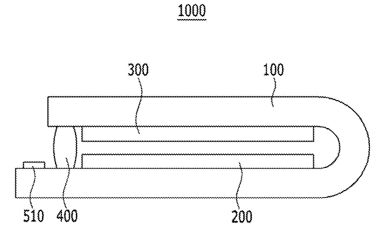
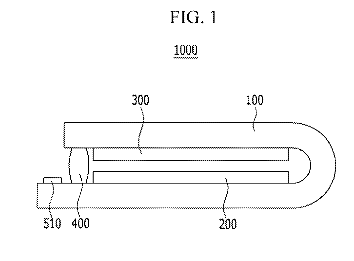
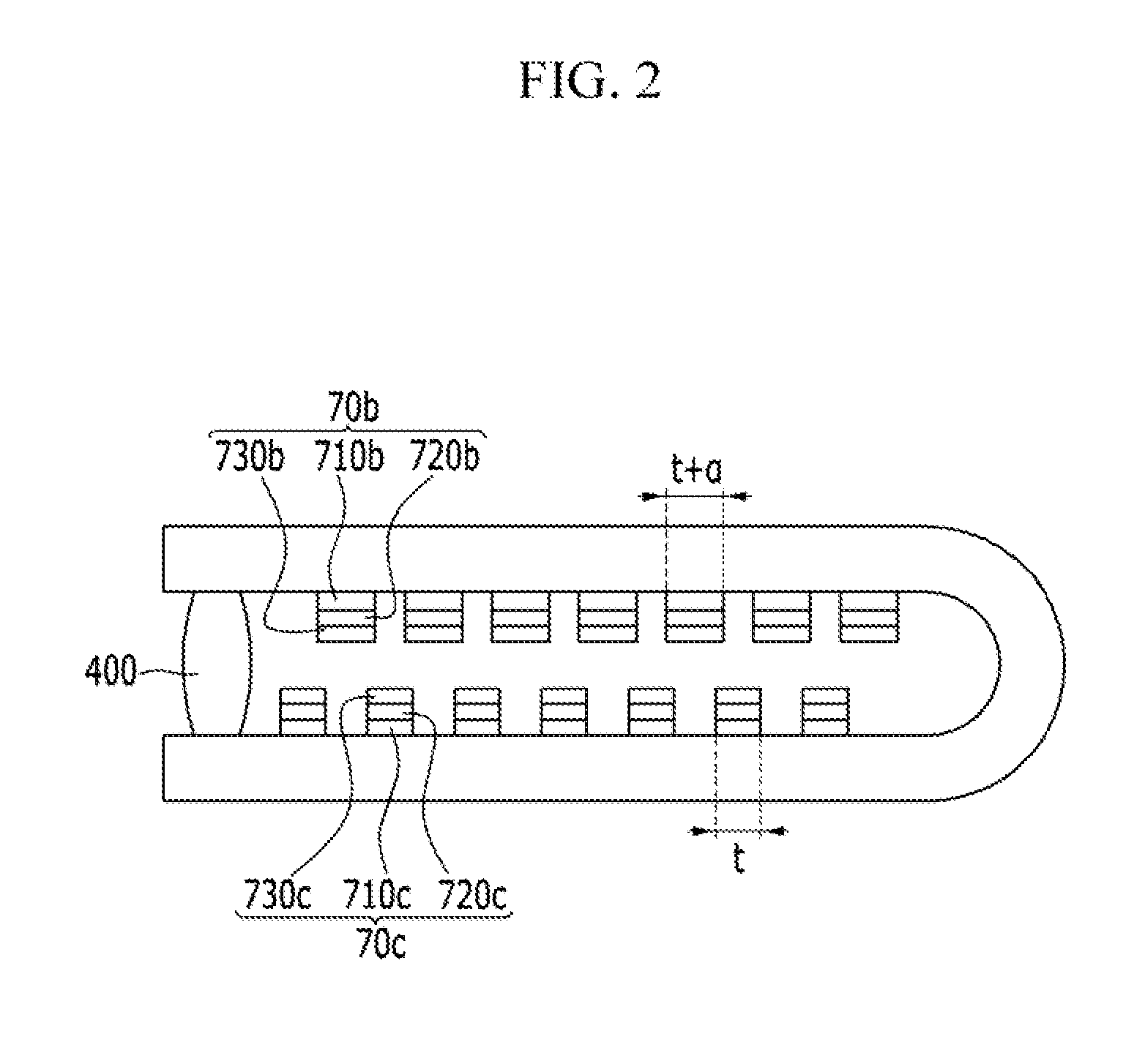
The present invention is an organic light emitting diode display that has improved luminance and prevented light reflection. It achieves this by overlapping the organic light emitting layers without reducing the light emitting region. Additionally, even when multiple light emitting units are not laminated, the display achieves higher luminance and reduces luminance loss due to overlapping.

Problems solved by technology

However, since units formed of a hole loading layer, the light emitting layer, and an electron loading layer should be repeatedly laminated in order to laminate loading layers constituting organic light emitting layers in plural, there is a problem in that a deposition process and costs are increased.
Furthermore, there is a problem in that a light emitting area is reduced due to overlapping of the organic light emitting layers or light emitted from the organic light emitting layers laminated on an upper portion is reflected by the organic light emitting layers laminated on a lower portion to reduce efficiency.

Method used


Image

  • Organic light emitting diode display
  • Organic light emitting diode display
  • Organic light emitting diode display

Examples


Embodiment Construction

[0036]The present invention will be described more fully hereinafter with reference to the accompanying drawings, in which exemplary embodiments of the invention are shown. As those skilled in the art will realize, the described embodiments may be modified in various different ways, all without departing from the spirit or scope of the present invention.

[0037]In the drawings, the thickness of layers, films, panels, regions, etc. are exaggerated for clarity. Like reference numerals designate like elements throughout the specification. It will be understood that when an element such as a layer, film, region, or substrate is referred to as being “on” another element, it can be directly on the other element or intervening elements may also be present. In contrast, when an element is referred to as being “directly on” another element, there are no intervening elements present.

[0038]Hereinafter, an organic light emitting diode display according to an exemplary embodiment of the present in...


PUM


Abstract

The present invention relates to an organic light emitting diode display, and in order to improve luminance, the organic light emitting diode display includes a flexible substrate bent at least one time, a first display unit positioned on the flexible substrate and including a plurality of first light emitting diodes, and a second display unit positioned on the flexible substrate and including a plurality of second light emitting diodes, in which a width of each second light emitting diode is larger than the width of each first light emitting diode.

Description

CLAIM OF PRIORITY[0001]This application claims priority to and the benefit of Korean Patent Application No. 10-2013-0094419 filed in the Korean Intellectual Property Office on Aug. 8, 2013, the entire contents of which are incorporated herein by reference.BACKGROUND OF THE INVENTION[0002]1. Field of the Invention[0003]The present invention relates to an organic light emitting diode display.[0004]2. Description of the Related Art[0005]An organic light emitting diode display is a self-light emitting display device displaying an image by using an organic light emitting diode emitting light. Since the organic light emitting diode display, unlike a liquid crystal display, does not require a separate light source, a thickness and a weight thereof may be relatively reduced. Furthermore, since the organic light emitting diode display has high quality characteristics such as low power consumption, high luminance, and a high reaction speed, the organic light emitting diode display receives at...

Claims


Application Information

Patent Timeline
Patent Type & Authority Applications(United States)
IPC IPC(8): H01L27/32
CPCH01L27/3244Y02E10/549H10K59/121H10K59/128H10K77/111H10K2102/311H10K59/8722H10K59/8791H10K59/12H10K2102/3031H10K2102/3026H10K50/8426
Inventor NAIJO, TSUYOSHI
Owner SAMSUNG DISPLAY CO LTD
Features
  • R&D
  • Intellectual Property
  • Life Sciences
  • Materials
  • Tech Scout
  • Unparalleled Data Quality
  • Higher Quality Content
  • 60% Fewer Hallucinations
Learn More