Device and method for estimating secondary cell status

Inactive Publication Date: 2015-02-12
PANASONIC EV ENERGY CO LTD
View PDF8 Cites 31 Cited by
  • Summary
  • Abstract
  • Description
  • Claims
  • Application Information

AI Technical Summary

Benefits of technology

[0018]According to the present invention, an optimum model is selected by use of an actually detected voltage value, whereby an optimum mode

Problems solved by technology

Although a technique for estimating an internal status of the secondary cell by use of a preset model is effective, an estimation error will increase if the preset model does not adapt to an actual behavior of the second

Method used


Image

  • Device and method for estimating secondary cell status
  • Device and method for estimating secondary cell status
  • Device and method for estimating secondary cell status

Examples


Example

First Embodiment

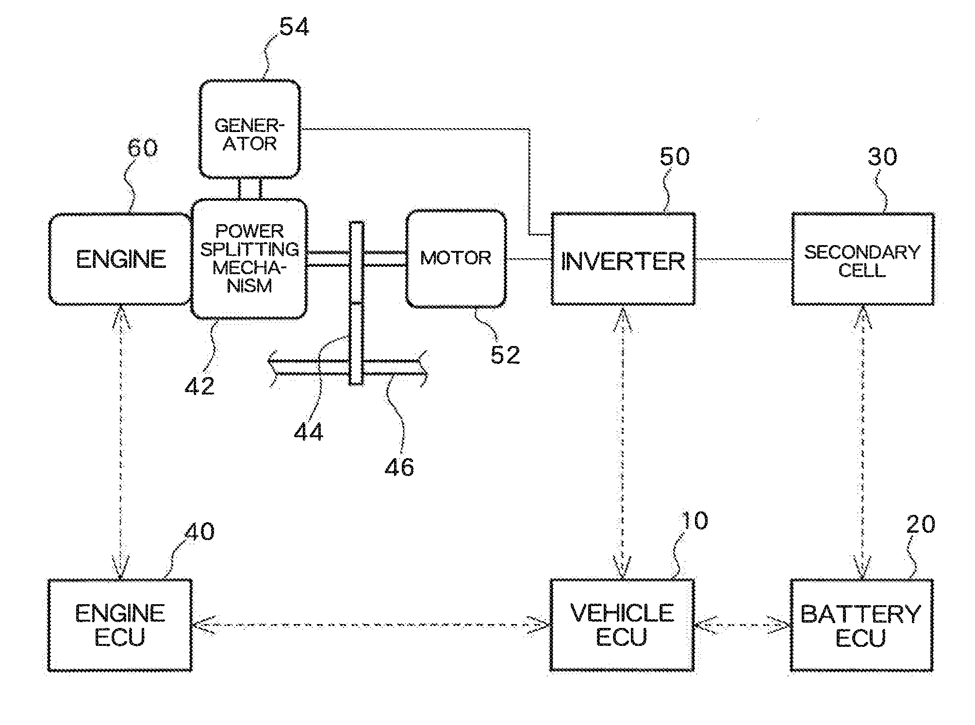
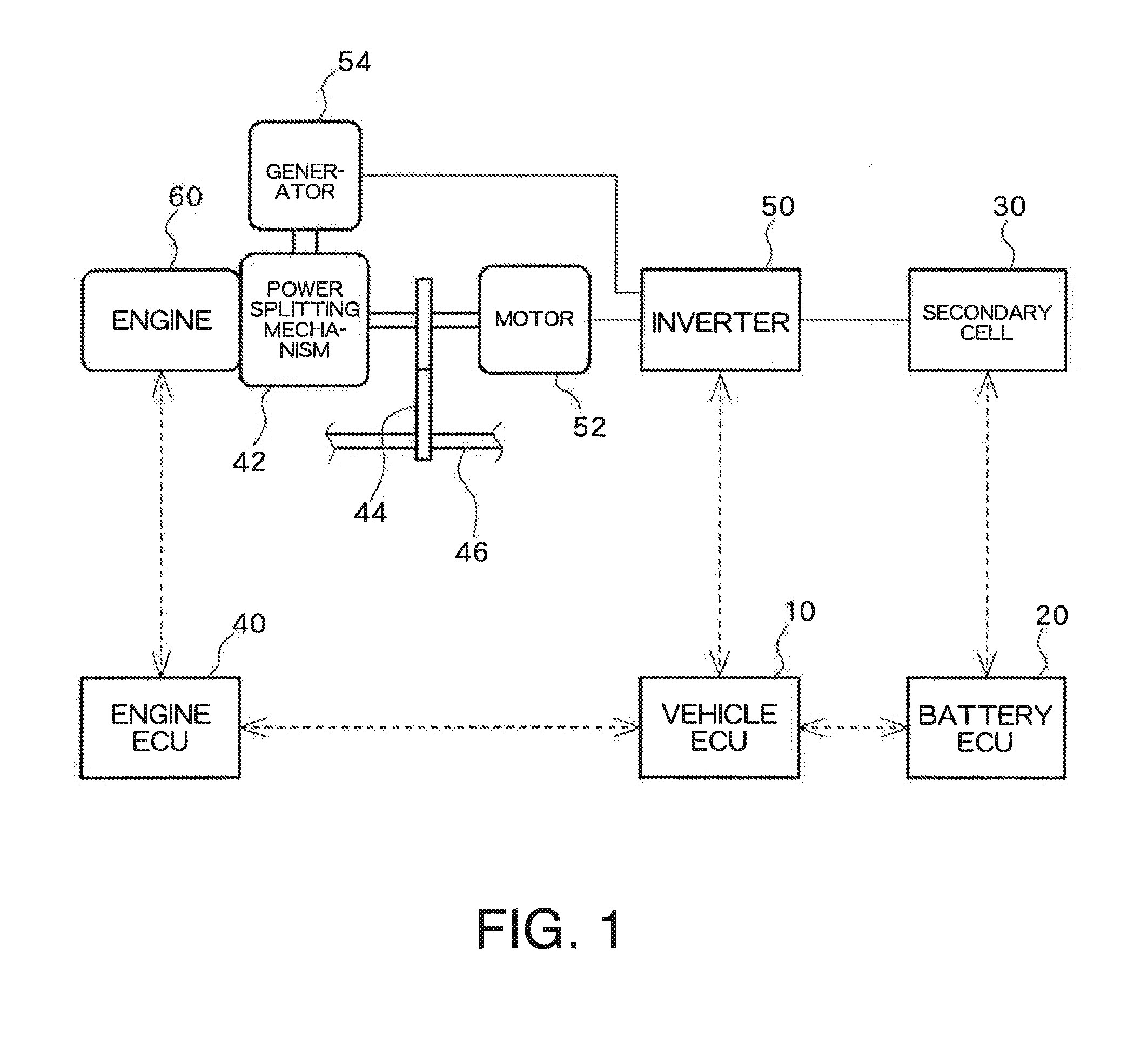
[0034]FIG. 1 illustrates a general configuration of a hybrid electric vehicle. A vehicle ECU 10 controls an inverter 50 and an engine ECU 40. The engine ECU 40 controls an engine 60. A battery ECU 20 acts as a state-of-charge estimation device and estimates a state of charge (SOC) of a secondary cell 30 by receiving from the secondary cell 30 data pertaining to a battery voltage V, a charge-and-discharge current I, a battery temperature T, and the like. The battery ECU 20 transmits battery data, like an SOC and a battery temperature of the second cell 30, to the vehicle ECU 10. The vehicle ECU 10 controls the engine ECU 40, the inverter 50, and others, on the basis of various types of battery data, thereby controlling charge and discharge of the secondary cell 30.

[0035]The secondary cell 30 supplies power to a motor 52. The inverter 50 converts d.c. power supplied from the secondary cell 30 into a.c. power during discharge of the secondary cell 30, supplying the a.c....

Example

Second Embodiment

[0091]In the first embodiment, an optimum model is set, and parameters of the optimum model are next optimized. Conversely, however, parameters of respective models are first optimized, and an optimum model can also be set subsequently.

[0092]FIG. 12 illustrates a processing flowchart of the control section 28 of the embodiment. The processing flowchart differs from its counterpart illustrated in FIG. 3 in that parameters of respective models are optimized (S303) and that model outputs are then evaluated (S304), thereby setting an optimum model (S305). After the optimum model is set, the status of the secondary cell 30; specifically, an estimated SOC value, is output by use of the optimum model as in the case with FIG. 3 (S306).

[0093]Parameter optimization is similar to that described in connection with the first embodiment and performed by use of a measured current value and a measured voltage value in accordance with the recursive least square algorithm. Accordingl...

Example

Third Embodiment

[0099]In the first embodiment, after an optimum model selected from a plurality of models is set, parameters of the model are optimized. In the second embodiment, after parameters of a plurality of models are optimized, an optimum model is set. Each of the embodiments has its merits and demerits. Namely, the method described in connection with the first embodiment exhibits a relatively low degree of accuracy but is advantageous in that processing can be speeded up. The method described in connection with the second embodiment involves consumption of much processing time but is advantageous in a relatively higher degree of accuracy. Parameter optimization processing involves a relatively large amount of processing. When all models are subjected to parameter optimization, much time is eventually consumed. Accordingly, it is preferable to select an appropriate method depending on processing capability of the processor of the control section 26. When the processor has a ...


PUM


Abstract

Provided is a device for estimating secondary cell status using multiple models. The device for estimating secondary cell status uses multiple models, model 1, model 2, and model 3, to estimate the status of respective secondary cells. An arithmetic unit compares the estimated voltage values obtained from model 1, model 2, and model 3 with measured voltage values, sets the model having the highest correlation as the optimal model, optimizes the parameters of such model, and estimates secondary cell status.

Description

TECHNICAL FIELD[0001]The present invention relates to a device and a method for estimating a secondary cell status and, more particularly, to a status estimation technique using a plurality of battery models.BACKGROUND ART[0002]Hitherto-known techniques include estimating a charge status (SOC: State of Charge) of a secondary cell, such as a nickel-metal hydride secondary cell and a lithium ion secondary cell and controlling charge and discharge of the secondary cell in accordance with the thus-estimated SOC.[0003]Patent Document 1 to be referred to hereunder discloses a battery management system comprised of: a sensing section for measuring a charge-and-discharge current flowing into a battery and a temperature and a terminal voltage of the battery; a prediction section for presuming an SOC of the battery by integration of the charge-and-discharge current; a data rejection section for generating data pertinent to an error attributable to a measurement model in accordance with a rate...

Claims


Application Information

Patent Timeline
IPC IPC(8): G01R31/36
CPCG01R31/3648G01R31/3658G01R31/3624H01M10/48H01M10/425H01M10/482H01M10/486H01M2010/4271B60L58/10G01R31/367G01R31/396G01R31/3842Y02T10/70Y02E60/10H02J7/0048H02J7/0013
Inventor AKAMINE, NAOSHI
Owner PANASONIC EV ENERGY CO LTD
Why Eureka
Try Eureka