
Compressed air supply installation and pneumatic system

a compressed air supply and installation technology, applied in the direction of positive displacement liquid engine, piston pump, separation process, etc., can solve the problems of reducing and reducing the space of the installation. , to achieve the effect of improving the ventilation and/or drying output improving the acoustic performance of the compressed air supply installation, and saving space design

Active Publication Date: 2015-02-19
ZF CV SYST EURO BV
View PDF2 Cites 10 Cited by
  • Summary
  • Abstract
  • Description
  • Claims
  • Application Information

AI Technical Summary

Benefits of technology

The present invention is about an improved and space-saving compressed air supply installation for a pneumatic unit, which is designed to reduce noise and improve its performance. The invention involves arranging a vent valve arrangement and an air drier in a compact way, and improving their output. The installation also involves utilizing the available space by designing a recess in the drying container of the air drier for housing the vent valve arrangement. The recess is formed by the wall of the drying container and creates a free space where the solenoid valve arrangement is placed, which improves acoustics and helps to dry the granulate using waste heat. Overall, the invention provides a more efficient and compact design for a compressed air supply installation.

Problems solved by technology

This represents an unnecessary waste of dry air, particularly in the event that a suitable flexible, rapid and yet reliable actuation of the compressed air supply installation with a correspondingly high actuation rate should be necessary for the above applications.
Although a main vent valve that can be configured with a comparatively large nominal width can be pneumatically pre-controlled via the control valve provided with a comparatively small nominal width, an arrangement of this kind designed for the indirect connection of a pressure volume is comparatively expensive.
These and other solutions from the prior art for an air drier have proved to be comparatively demanding in terms of installation space.

Method used


Image

  • Compressed air supply installation and pneumatic system
  • Compressed air supply installation and pneumatic system
  • Compressed air supply installation and pneumatic system

Examples


Embodiment Construction

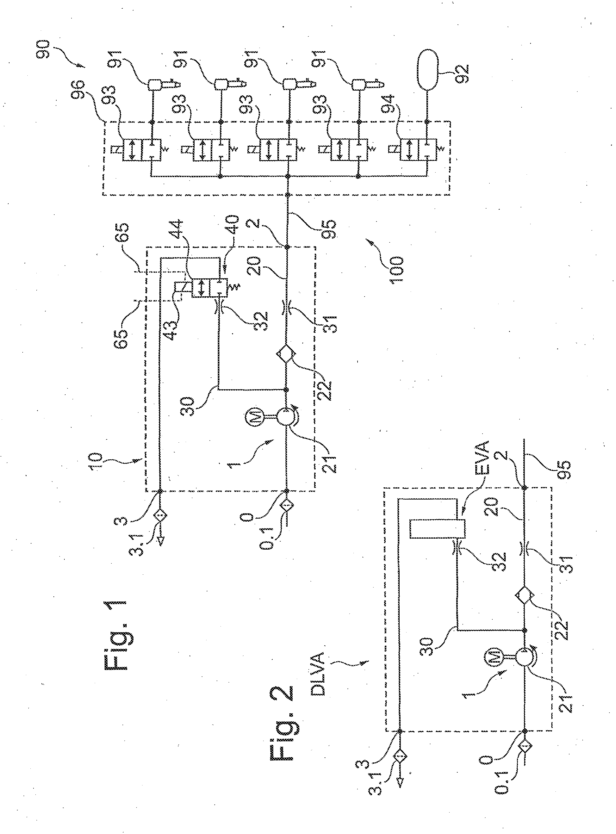
[0122]FIG. 1 shows a pneumatic system 100 with a compressed air supply installation 10 and a pneumatic system 90, in the form of an air suspension system in this case. The same reference numbers are used for identical or similar parts or parts with an identical or similar function, where appropriate. The air suspension system exhibits a number of bellows 91, which are each assigned to a wheel of a vehicle, and also a reservoir 92 for storing quickly accessible compressed air for the bellows 91. The bellows 91 and the reservoir 92 are connected to a common pneumatic line forming a header 95, which also creates the pneumatic connection between the compressed air supply installation 10 and the pneumatic system 90. A normally closed solenoid valve 93 is connected upstream of the bellows 91 in each case as a level control valve and a normally closed solenoid valve 94 is connected upstream of the reservoir 92 as a reservoir control valve. The solenoid valves 93, 94 are arranged in a valve...


PUM


Abstract

A compressed air supply installation for operating a pneumatic installation, especially an air suspension installation of a vehicle, includes an air supply unit and an air compression unit for supplying a compressed air supply unit with compressed air, a pneumatic connection, especially a bleeding line, comprising a bleeding valve and a bleeding port for bleeding air, and a pneumatic connection, especially a compressed air supply line having an air drier and a compressed air port for supplying the pneumatic installation with compressed air. The air drier has a drier container through which compressed air can flow and which contains a desiccant. The drier container has a wall forming a desiccant-free recess, and at least part of the bleeding valve system is arranged in the recess.

Description

CROSS-REFERENCE TO RELATED APPLICATIONS[0001]This application is a continuation of and claims the benefit of U.S. Ser. No. 13 / 993,283 filed Jun. 11, 2013; as such, this application claims the benefit of and priority to PCT / EP2011 / 005864 filed on Nov. 22, 2011, and DE 102010054704.2 filed on Dec. 16, 2012, the disclosures of all of which are hereby incorporated herein by reference in their entireties.FIELD OF THE INVENTION[0002]The invention generally relates to a compressed air supply installation and to a pneumatic system having such compressed air supply installation.BACKGROUND OF THE INVENTION[0003]Compressed air supply installations are used in all kinds of vehicles, particularly to supply vehicle air suspension systems with compressed air. Air suspension systems may also include level control mechanisms, with which the distance between the vehicle axle and the vehicle body can be set. An air suspension system in a pneumatic system comprises a number of air bellows pneumatically...

Claims


Application Information

Patent Timeline
Patent Type & Authority Applications(United States)
IPC IPC(8): B60G17/052F04B17/03F04B39/16
CPCB60G17/0523F04B17/03F04B39/16B01D53/261B60G2202/152B60G2300/07B60G2500/2012B60G2500/2021B60G2500/2044B60G2600/26B60G2600/66F16K31/0651F16K31/0658F16K31/0675Y10T137/86051B60G17/052
Inventor FRANK, DIETERMEISSNER, FRANK
Owner ZF CV SYST EURO BV
Learn More