Circuit arrangement

a circuit arrangement and circuit technology, applied in the field of circuit arrangement, can solve the problems of early disconnect, inability to operate, unacceptable light output and/or optical flicker, etc., and achieve the effect of enhancing the energy efficiency of the circuit arrangement and being energy efficien

Active Publication Date: 2015-02-19
KONINKLIJKE PHILIPS ELECTRONICS NV
View PDF4 Cites 32 Cited by
  • Summary
  • Abstract
  • Description
  • Claims
  • Application Information

AI Technical Summary

Benefits of technology

[0065]According to another preferred embodiment said additional boost current pulses is applied in the half-cycles when “test loading” occurs, i.e. when a current wave shape is applied that keeps the TRIAC in conduction substantially/almost until the zero crossing of the mains, i.e. the before mentioned intended wide conduction interval operation. During half-cycles where a narrow conduction interval is applied, the current pulse injector is disabled so that no current puls

Problems solved by technology

On its turn this oscillation may cause “early disconnect” of a TRIAC when a phase-cut dimmer is used to provide operating power to the lamps.
Here, the early interruption of energy delivery to the lamp with (intended) wide conduction interval may cause one of the following failures, resulting in an unacceptable light

Method used


Image

  • Circuit arrangement
  • Circuit arrangement
  • Circuit arrangement

Examples


Embodiment Construction

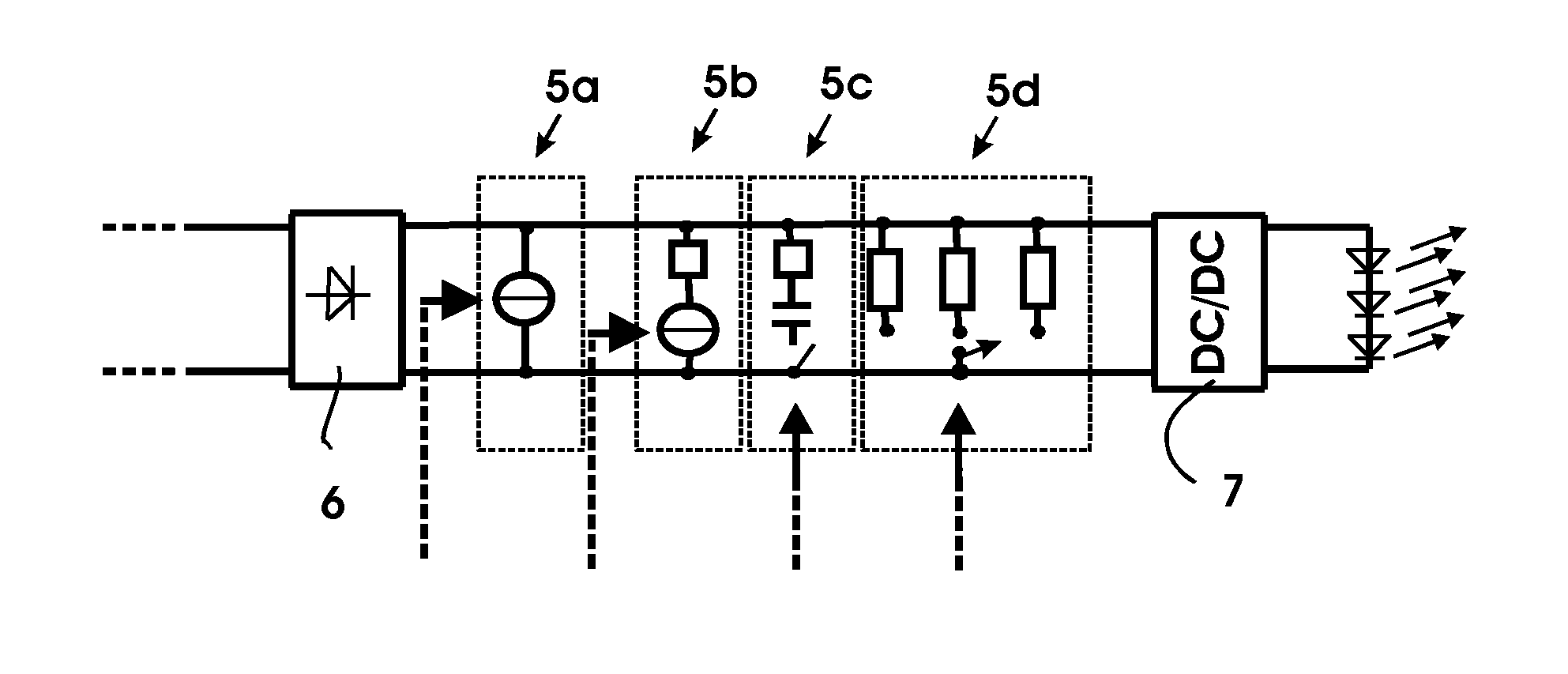
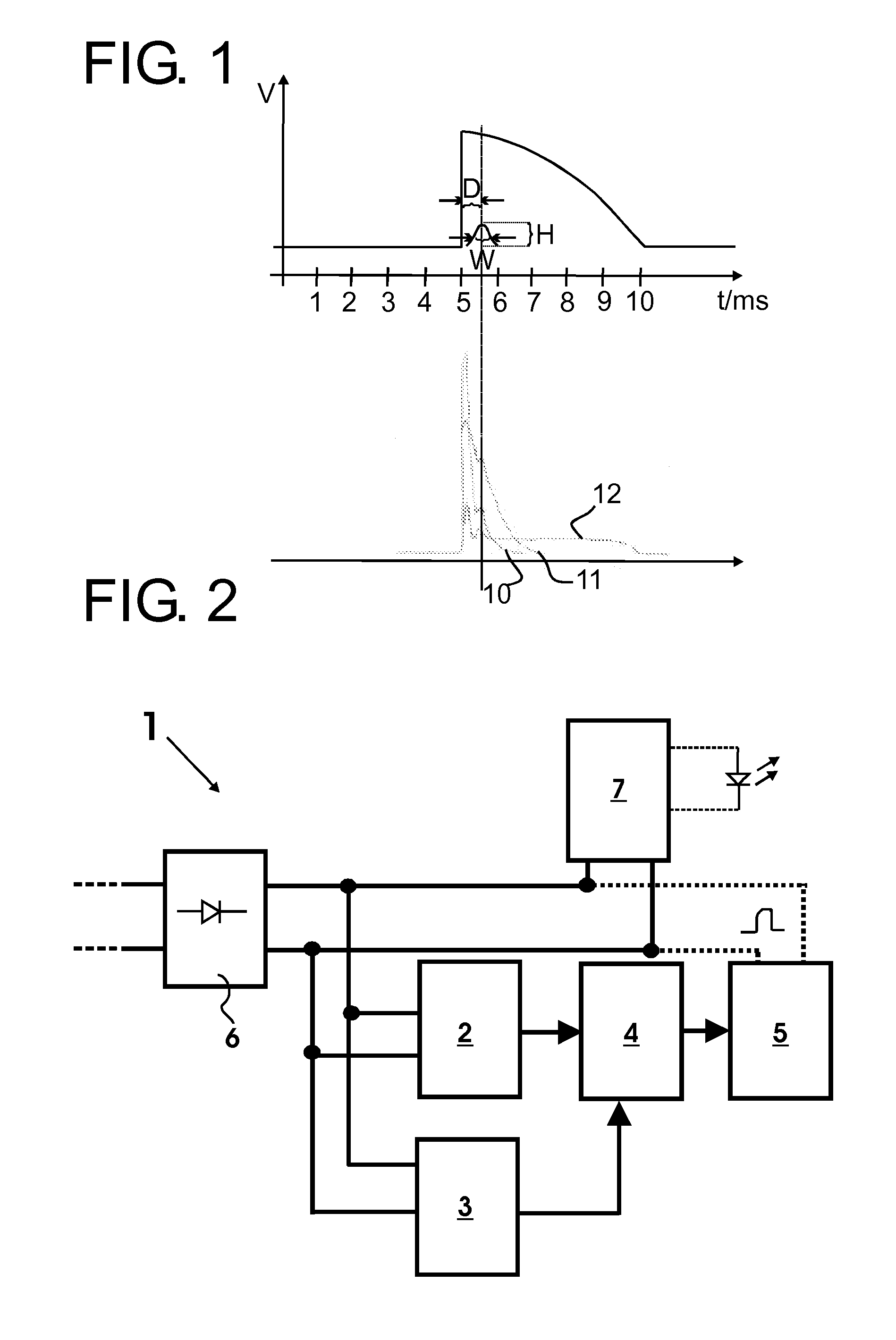
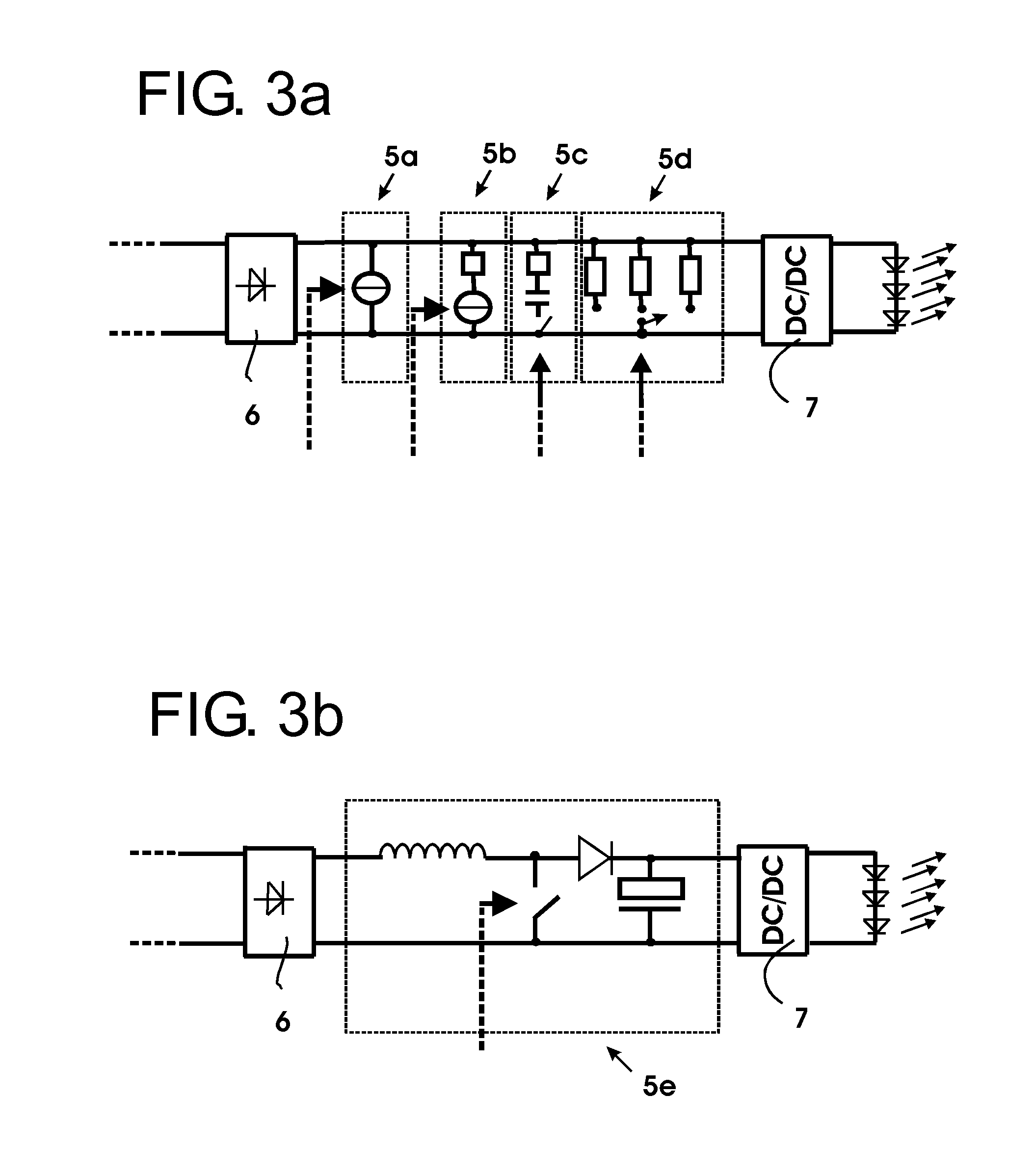
[0124]A basic embodiment of a first aspect invention is in the following explained with reference to FIGS. 1-4. According to the present aspect of the invention it is proposed to provide a circuit arrangement which enhances the compatibility when operating multiple LED lamps in parallel with a phase-cut power supply dimmer. The circuit arrangement is adapted to draw an additional boost current pulse within a delay time of 200 to 700 μs which has been found to in particular reduce optical flicker in the output light of the LED lamps.

[0125]The present aspect of the invention is based on the recognition of the inventors that certain types of currently available LED lamps, in the following referred to as “first type of lamps” employ the principle of energy intake during a narrow conduction interval. The negative dI / dt that is created by the lamps with the narrow conduction interval induces an oscillation in the LC circuitry of a connected phase-cut power supply / dimmer and / or EMI filters...


PUM


Abstract

A circuit arrangement (1), a detection circuit (50, 70) and an LED driver circuit (100, 110) is disclosed for operating at least one lighting unit, such as an LED unit, with a phase-cut operating voltage. The circuit arrangement (1) comprising at least an input (6) for receiving a phase-cut operating voltage from said power supply and/or an output (7) for connection to said at least one lighting unit and a pulse injection circuit, configured to determine a phase-cut operation of said power supply and to draw a current pulse from said power supply within a delay time between 200-700 μs after said phase-cut operation to provide a stable operation of said LED unit with the phase-cut power supply. The detection circuit (50,70) comprises at least an input (6) for receiving a phase-cut operating voltage from said power supply and a lamp compatibility detector (52, 72), configured to determine the presence of a parallel lamp (57), connected in parallel with the detection circuit (50, 70) to said phase-cut power supply during operation and to provide a compatibility signal to a LED driver circuit (100, 110) corresponding to the determination of said parallel lamp (57), so that said driver circuit (100, 110) is set between a normal operating mode and a compatibility mode in dependence of the presence of said parallel lamp (57).

Description

TECHNICAL FIELD[0001]The present invention relates to the field of lighting and in particular to a circuit arrangement for operating a lighting unit with a phase-cut power supply, an LED lamp, a lighting system and a method of operating a lighting unit.BACKGROUND ART[0002]Today, LED-based lighting units are being used for many applications. The low power consumption and long lifetime of LEDs make them a very useful alternative to conventional light sources like incandescent lamps or light tubes. Hence, not only new-designed lighting equipment often utilizes LEDs, but in many markets LED products are being used to replace other light-sources like incandescent or halogen light sources, for instance. These so-called retrofit products have to be compatible with existing lighting / power supply systems.[0003]In many lighting system topologies, dimmed light is needed. In the latter case, a phase-cut power supply / dimmer typically is placed between the lamp and mains. Here, the time evolution...

Claims


Application Information

Patent Timeline
IPC IPC(8): H05B33/08H05B44/00
CPCH05B33/08H05B45/48H05B45/10H05B45/375H05B45/3725H05B47/17H05B45/38H05B45/385
Inventor BOONEN, PAUL THEODORUS JACOBUSMALYNA, DMYTRO VIKTOROVYCHKURT, RALPHRADERMACHER, HARALD JOSEF GUNTHERHONTELE, BERTRAND JOHAN EDWARD
Owner KONINKLIJKE PHILIPS ELECTRONICS NV
Why Eureka
Try Eureka