
Stabilizing a Power Combining Power Supply System

Active Publication Date: 2015-02-19
QUANTANCE
View PDF0 Cites 53 Cited by
  • Summary
  • Abstract
  • Description
  • Claims
  • Application Information

AI Technical Summary

Benefits of technology

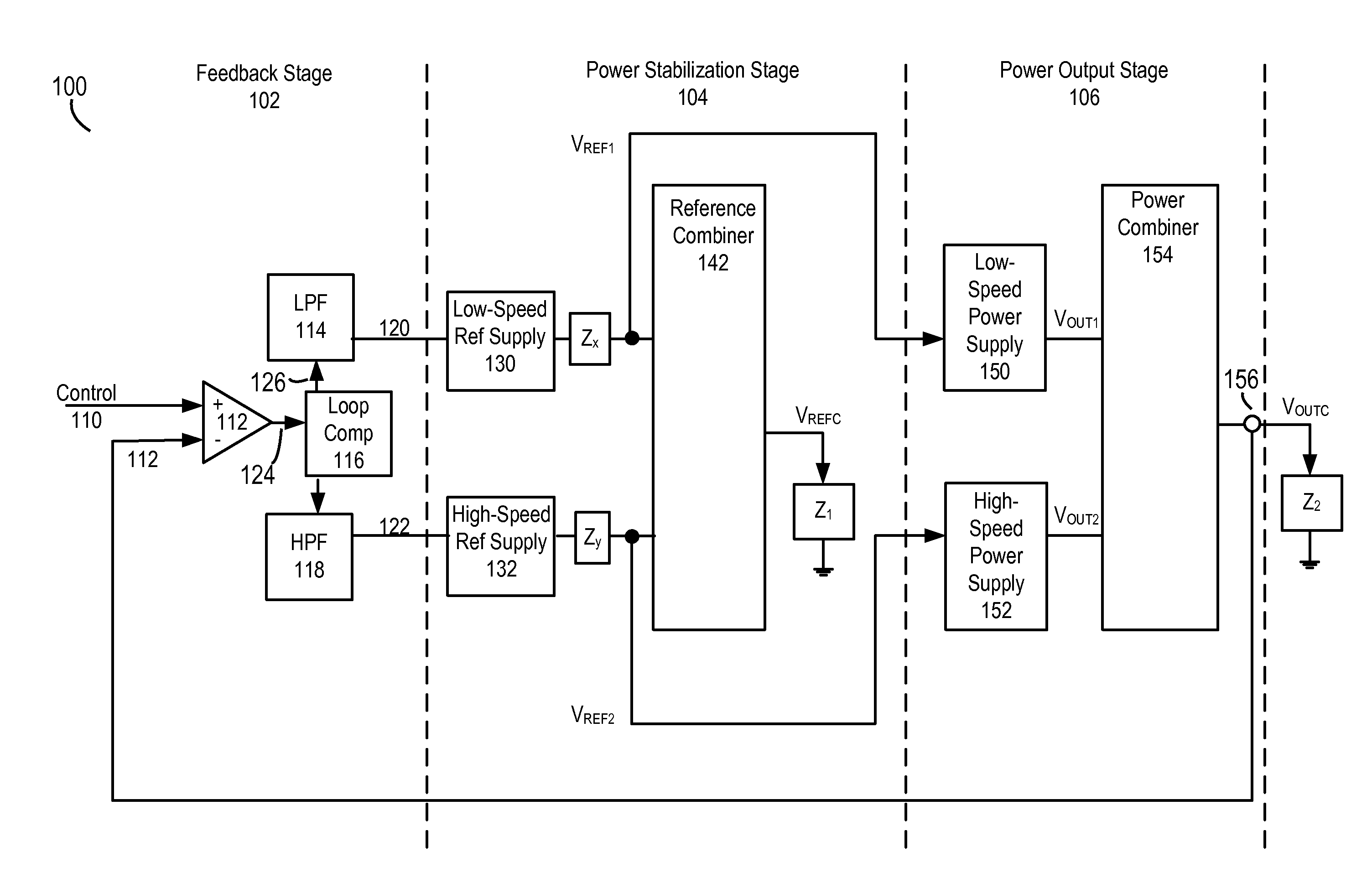
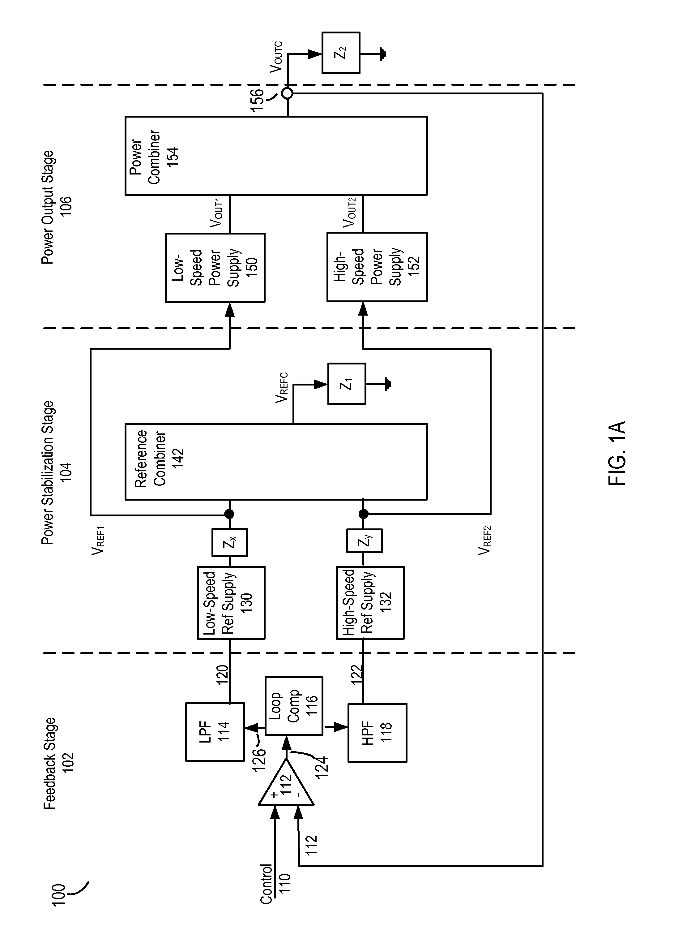
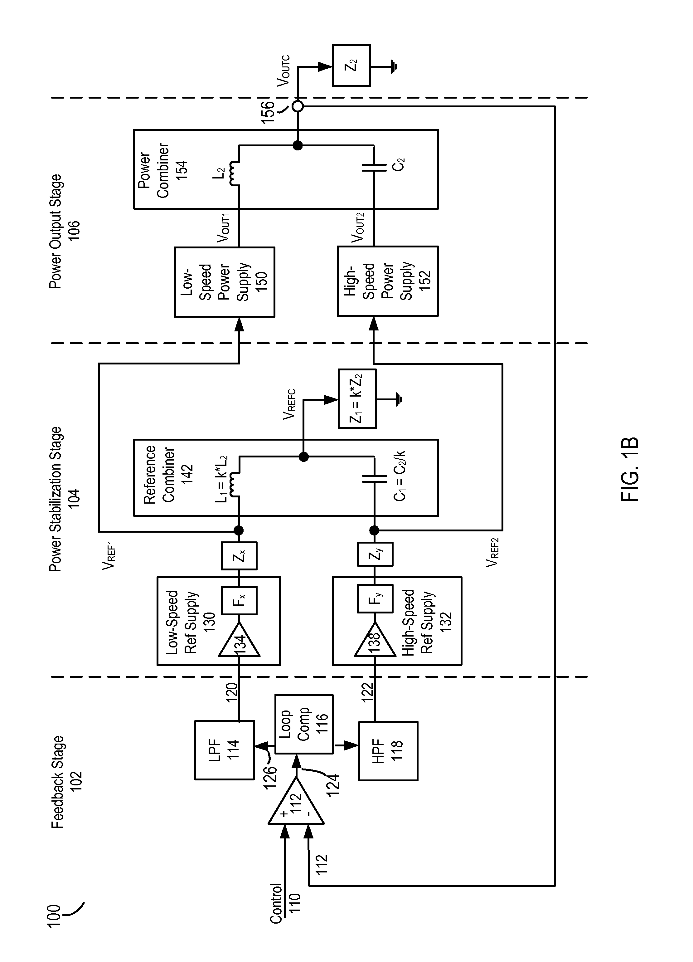
The present invention is a power supply system that generates a combined reference signal for driving a reference load. The system includes a power stabilization stage that combines a first reference signal and a second reference signal with different frequency ranges. The system also includes a feedback stage that generates power supply control signals for controlling the power stabilization stage based on the difference between a control signal and a feedback signal. The system can be used in RF PA systems to provide a stable supply voltage or bias. The technical effects of the invention include reducing resonance in the combined output and improving the stability of the power supply system.

Problems solved by technology

A typical switched-mode power supply (SMPS) circuit achieves high efficiency, but cannot deliver sufficiently high frequency components of the power, because the low switching frequencies commonly used in these types of regulators (a limitation largely imposed by the magnetics) limits the regulator's bandwidth.
Linear regulators, on the other hand, may be designed to deliver high frequency components, but the power conversion efficiency of such a linear regulator is poor.
Thus neither a common SMPS nor a linear regulator can meet this need.
The configuration of inductor and capacitor causes unwanted ringing that is counteracted by increasing the output impedance of the SMPS and the linear regulator.
However, increasing the output impedance of the power supplies has the negative consequence of reducing the efficiency of the power supply circuit.

Method used


Image

  • Stabilizing a Power Combining Power Supply System
  • Stabilizing a Power Combining Power Supply System
  • Stabilizing a Power Combining Power Supply System

Examples


Embodiment Construction

[0016]The Figures (FIG.) and the following description relate to preferred embodiments of the present disclosure by way of illustration only. It should be noted that from the following discussion, alternative embodiments of the structures and methods disclosed herein will be readily recognized as viable alternatives that may be employed without departing from the principles of the disclosed embodiments.

[0017]Reference will now be made in detail to several embodiments of the present disclosure, examples of which are illustrated in the accompanying figures. It is noted that wherever practicable similar or like reference numbers may be used in the figures and may indicate similar or like functionality. The figures depict embodiments of the present disclosure for purposes of illustration only. One skilled in the art will readily recognize from the following description that alternative embodiments of the structures and methods illustrated herein may be employed without departing from th...


PUM


Abstract

A power supply system comprising a power stabilization stage configured to combine a first reference signal having a first frequency range with a second reference signal having a second frequency range that is different than the first frequency range to generate a combined reference for driving a reference load. A first power supply (e.g. SMPS) is configured to generate a first output based on the first reference signal. A second power supply (e.g. linear regulator) is configured to generate a second output based on the second reference signal. A power combiner circuit is configured to combine the first output with the second output to generate a combined output for driving an output load.

Description

BACKGROUND[0001]1. Field of the Disclosure[0002]The present disclosure relates to a power supply and, more specifically, to stabilizing a power combining power supply system.[0003]2. Description of the Related Art[0004]Many electronic devices tend to require much more sophisticated power supplies for supplying power. For example, many electronics may require high frequency of operation, high overall efficiency, few components, and / or low ripple in the power supplied by the power supplies.[0005]More specifically, there is often a need for a power supply circuit that is capable of delivering power with high frequency components (fast changing voltage and current), at high overall power conversion efficiency. For example, an RF (Radio Frequency) PA (power amplifier) can be fed by an efficient power supply at a reduced voltage, allowing the PA to operate more efficiently (i.e., with lower power consumption). In these RF power amplifiers, the power supply must be capable of changing the ...

Claims


Application Information

Patent Timeline
IPC IPC(8): H02M3/06H03F3/189
CPCH03F3/189H02M3/06H03F1/0227H03F3/211H03F3/245H03F2200/102H03F2200/432H03F2200/555H02M3/1584H02M1/0045H03G3/20
Inventor VINAYAK, VIKAS
Owner QUANTANCE
Learn More