Method and device for safeguarding a hazardous working area of an automated machine

a technology for safeguarding and working areas, applied in the direction of instruments, mechanical equipment, image enhancement, etc., can solve the problems of large space occupation, difficult installation of protective devices, and inflexible protective devices

Active Publication Date: 2015-02-19
PILZ (COMPANY)
View PDF4 Cites 59 Cited by
  • Summary
  • Abstract
  • Description
  • Claims
  • Application Information

AI Technical Summary

Benefits of technology

[0010]Against this background, it is an object of the present invention to provide a method and a device of the type mentioned at the outset which, in the simplest and most efficient manner possible, make it possible for persons to flexibly stay in the hazardous working area of an automated machine, but with the safeguarding of the machine required for such a use and the required fail-safety being ensured.

Problems solved by technology

However, the installation of such protective devices is rather complicated and the protective devices require a large amount of space around a hazardous machine.
In addition, such protective devices are not very flexible when it comes to adapting the safeguarding of the hazardous working area to different operating situations of the machine.
A great challenge for such methods and devices is that the image processing, which is already complex anyway, must be fail-safe in terms of relevant machine safety standards, in particular EN 954-1 (already expired), EN ISO 13849-1 and IEC 61508, in order for such a device to be allowed for actual use safeguarding a hazardous machine.
Failure of the device itself must not result in the safeguarding of the machine being lost.
However, the known device has hitherto been able to detect only whether a foreign object is situated in a previously defined protection zone in order to slow down or stop a hazardous machine movement on the basis thereof.
Man-machine interaction in the immediate vicinity of man and machine and flexible adaptation to changing operating situations and / or on the basis of the type of foreign object, are not readily possible with the known device.
Corresponding modeling appears to be complicated and in any case limits flexibility since adaptation to new operating situations requires new modeling in each case.
However, DE 10 2007 007 576 A1 does not contain any indication that the evaluation of the 3-D images and the underlying modeling can provide the fail-safety required for safeguarding hazardous working areas.
The method described appears to be very computation-intensive and complex, and it is therefore doubtful whether the fail-safety and reaction speed required for the intended purpose can be achieved with modern computer performance.
However, none of the methods provides the fail-safety required for this intended purpose.

Method used


Image

  • Method and device for safeguarding a hazardous working area of an automated machine
  • Method and device for safeguarding a hazardous working area of an automated machine
  • Method and device for safeguarding a hazardous working area of an automated machine

Examples


Embodiment Construction

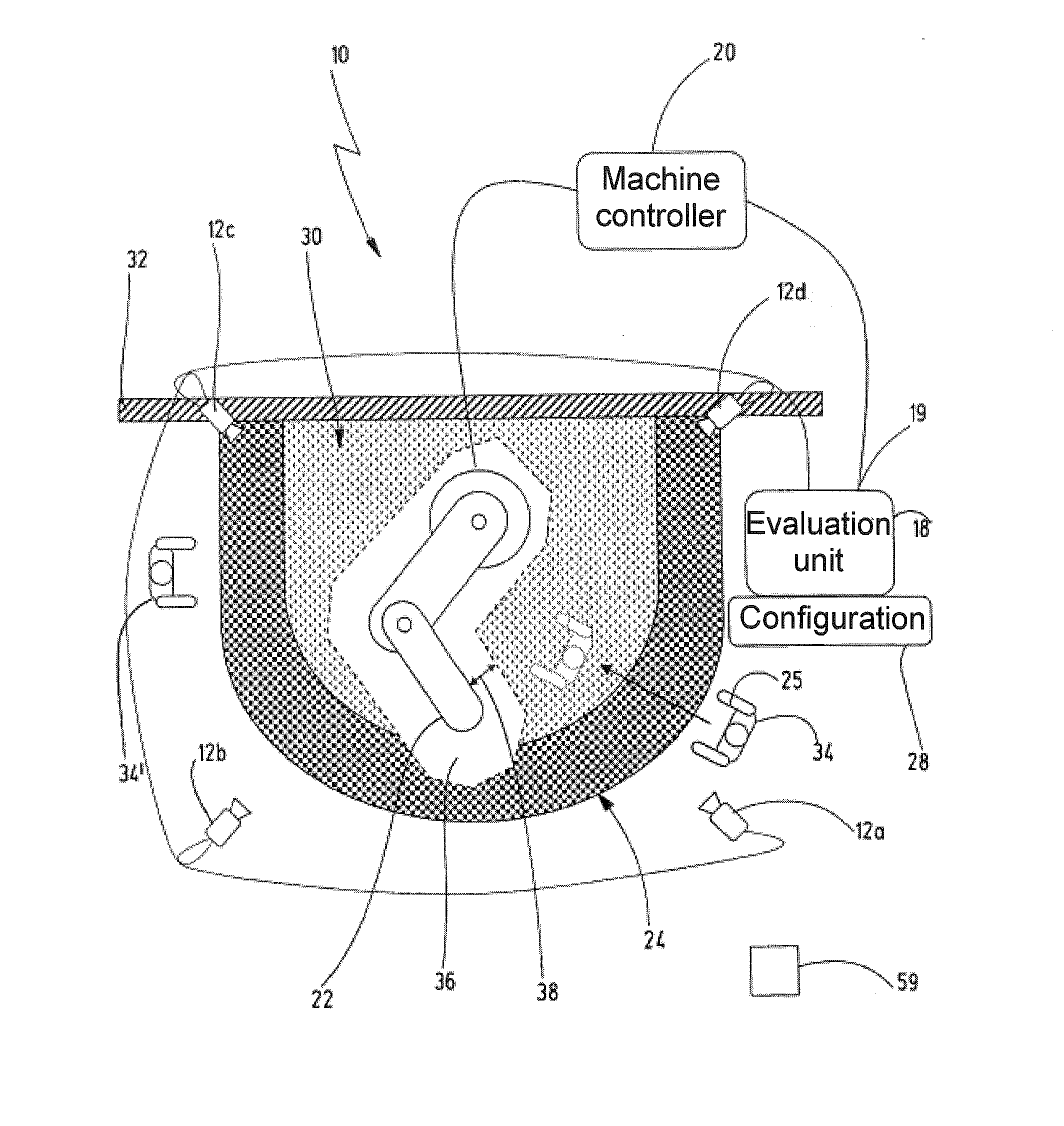
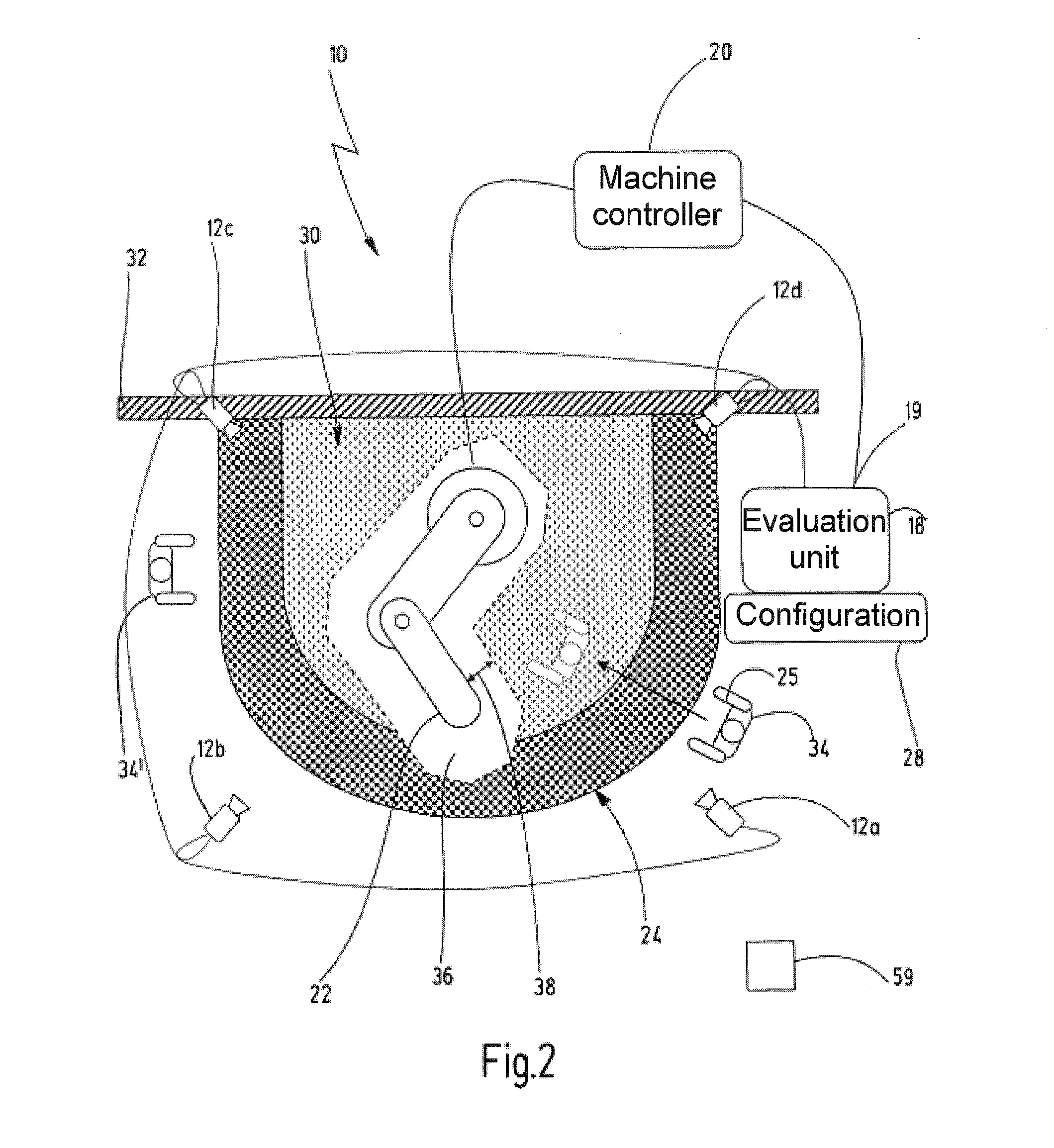
[0044]In FIGS. 1 and 2, a preferred exemplary embodiment of the novel device is denoted in its entirety with the reference numeral 10.

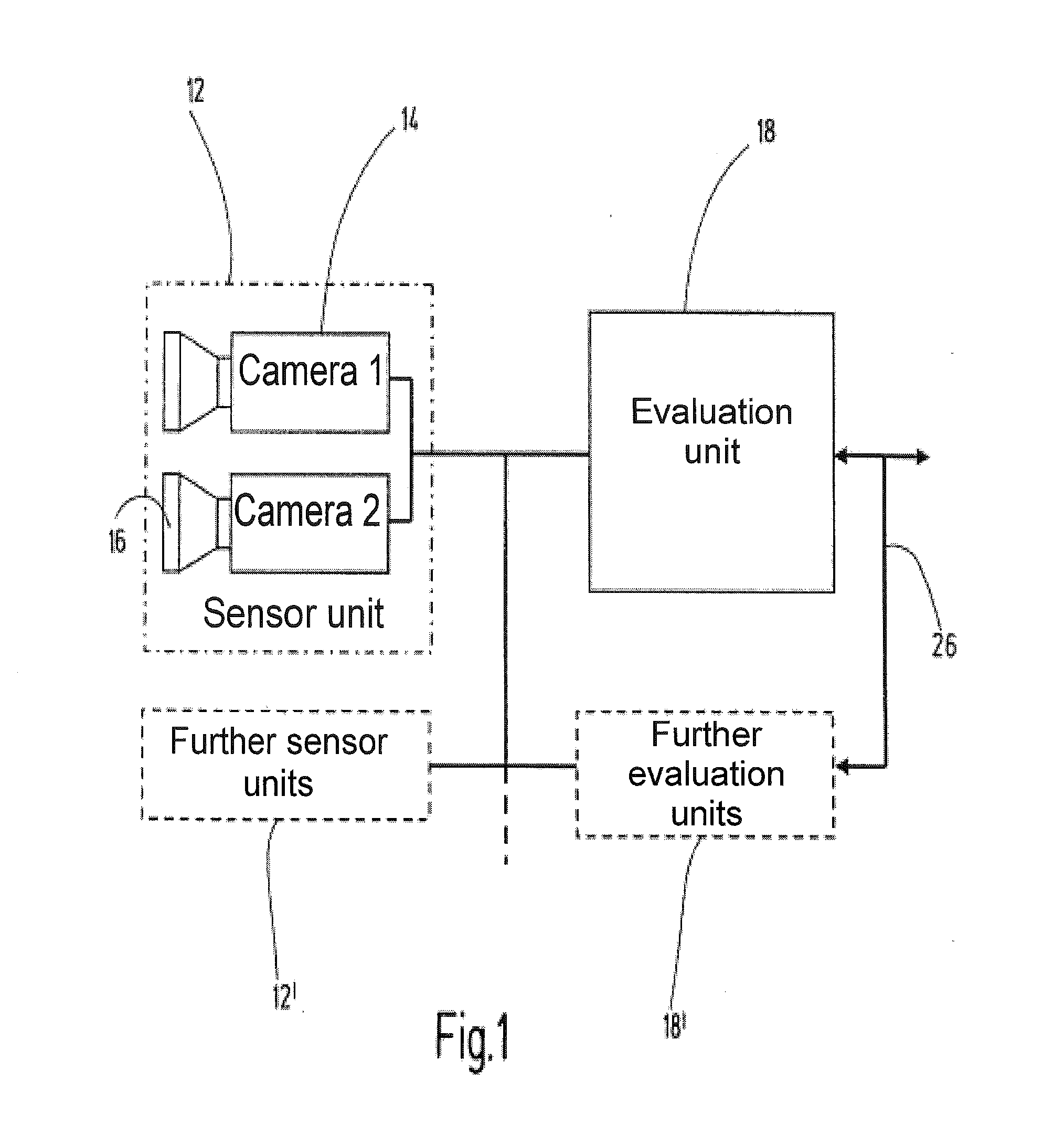
[0045]The device 10 comprises at least one sensor unit 12 which is designed to provide a respective current 3-D image of the hazardous working area of an automated machine at defined intervals of time. In one preferred exemplary embodiment, the sensor unit 12 is a stereo camera system having at least a first camera 14 and a second camera 16. The cameras 14, 16 provide two images of the working area to be safeguarded, which images are slightly offset with respect to one another. On account of the (known) offset between the cameras 14, 16 and using trigonometric relationships, the distance between the sensor unit 12 and objects in the working area can be determined using the camera images. A preferred sensor unit is described in US 2005 / 207618 A which was mentioned at the outset and which is completely incorporated here by reference.

[0046]In other exemp...


PUM


Abstract

A method and device for safeguarding a hazardous working area includes a camera system for generating successive 3-D images of the working area, and an evaluation unit comprising a fail-safe foreign object detector, a classifier, a person tracker and a comparator. The foreign object detector generates a first signal comprising a first item of position information, representative of the position of a foreign object in the protection zone. The classifier attempts to identify the foreign object as a person. The person tracker tracks an identified person using a series of current 3-D images and, after each new 3-D image, determines a second item of position information representing the current position of the identified person. If the position of the foreign object according to the first item of position information and the position of the identified person are different from one another, a control signal for stopping the machine is generated.

Description

CROSS-REFERENCE TO RELATED APPLICATIONS[0001]This application is a continuation of international patent application PCT / EP2013 / 054833, filed on Mar. 11, 2013 designating the U.S., which international patent application has been published in German language and claims priority from German patent application DE 10 2012 102 236.4 filed on Mar. 16, 2012. The entire contents of these priority applications are incorporated herein by reference.BACKGROUND OF THE INVENTION[0002]The present invention relates to a method and a device for safeguarding a hazardous working area of an automated machine. More particularly, the invention relates to a method and a device in which a respective current 3-D image of the working area is recorded and evaluated in order to avoid a risk to persons entering the working area.[0003]Traditionally, the hazardous areas of automated machines are closed off with mechanical barriers in the form of protective fences and guard doors and using light barriers, light gri...

Claims


Application Information

Patent Timeline
Patent Type & Authority Applications(United States)
IPC IPC(8): G06T7/00G06K9/62G06T7/20G06K9/32G06K9/00
CPCG06T7/0004G06K9/3241G06K9/00369G06T2207/30164G06K9/6267G06T2207/10012G06K2209/19G06T7/2086F16P3/142G06T7/285G06V40/103G06V2201/06G06F18/24
Inventor DOETTLING, DIETMARPILZ, THOMASFRANK, RUEDIGERHUFNAGEL, MARK
Owner PILZ (COMPANY)
Why Eureka
Try Eureka