
Light based skin treatment device avoiding liob in air

a skin treatment device and light-based technology, applied in the field of light-based skin treatment devices, can solve the problems of not all hairs or skin tissue are correctly hit, and appear to be much more harmful to the exit window than for liob

Active Publication Date: 2015-02-19
KONINKLIJKE PHILIPS ELECTRONICS NV
View PDF4 Cites 25 Cited by
  • Summary
  • Abstract
  • Description
  • Claims
  • Application Information

AI Technical Summary

Benefits of technology

The light-based skin treatment device described in the invention reduces or avoids the formation of LIOB in air. This is achieved by ensuring that the maximum power density in the focal spot in air remains below the threshold value required for LIOB formation. The device also uses a transparent glass or plastics exit window with a refractive index close to air, which prevents LIOB formation in air and its damaging effects on the window.

Problems solved by technology

However, in real operation not all hairs or skin tissue are correctly hit and LIOB is generated either in the applied immersion fluid, e.g. water, or in air, if e.g. an air bubble is present.
The side effects of the laser induced optical breakdown of gas molecules in air, such as shock wave, plasma and high power density of the light in the focal spot, have appeared to be much more harmful to the exit window than for LIOB in immersion fluids, hair or skin tissue.

Method used


Image

  • Light based skin treatment device avoiding liob in air
  • Light based skin treatment device avoiding liob in air
  • Light based skin treatment device avoiding liob in air

Examples


Embodiment Construction

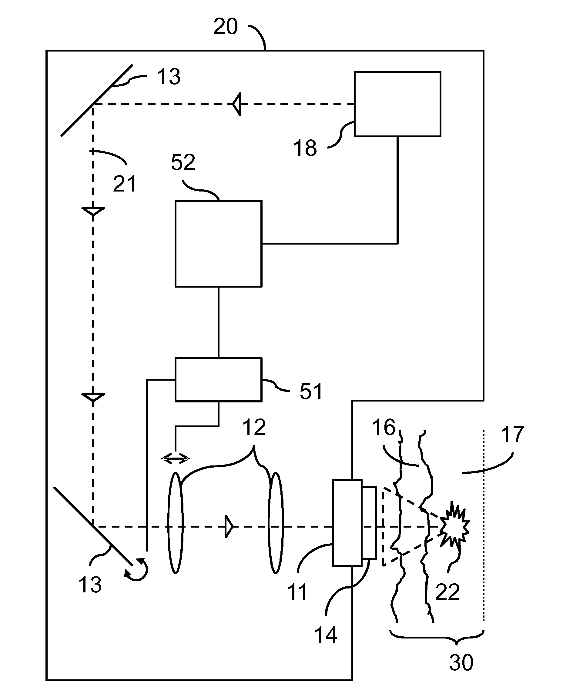
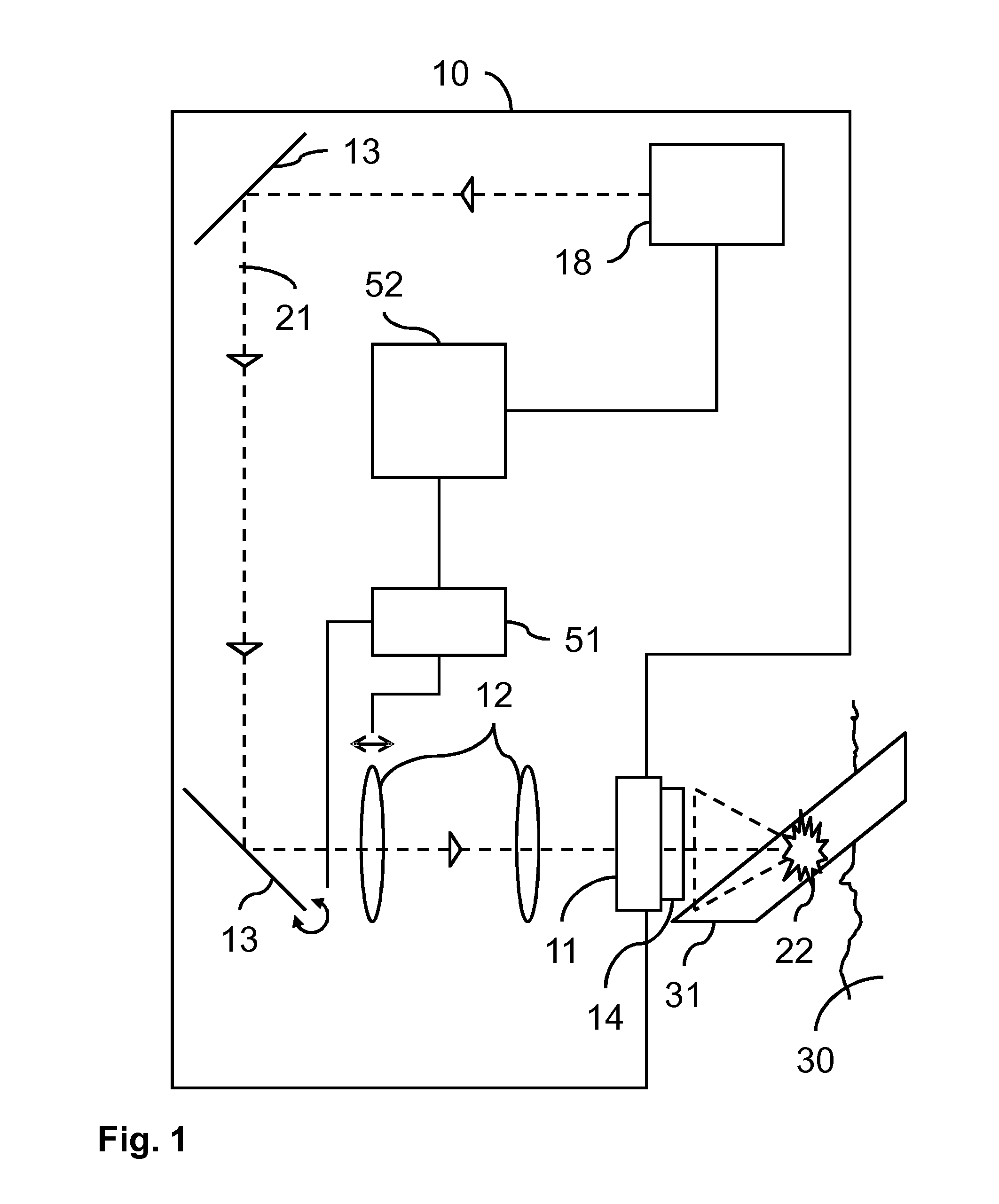
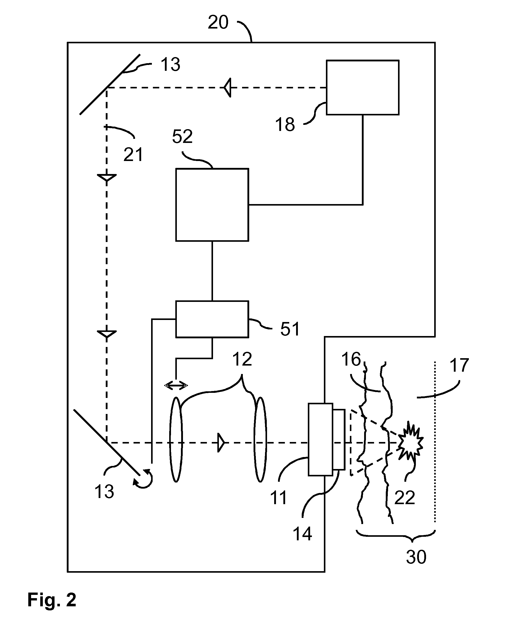
[0028]FIG. 1 schematically shows an optical shaver 10 according to the invention. The optical shaver comprises a light source 18 for providing an incident light beam 21 for cutting hairs 31 growing at human or animal skin 30. The incident light beam 21 is typically a pulsed laser. For example, Nd:YAG lasers with emission at 1064 nm or Er:YAG lasers with emission at 1645 nm are used for laser induced optical breakdown (LIOB) cutting of the hairs 31. Optical elements, such as lenses 12 and mirrors 13, are provided and form an optical system for focusing the pulsed laser beam 21 into a focal spot 22 in the hair 31. The optical elements 12, 13 may be adjustable by a focusing device 51 for adapting the exact position of the focal spot 22 when needed. For this purpose, e.g., the lenses 12 may be translated and / or the mirrors 13 may be rotated. A processor 52 is provided and coupled to, e.g., the light source 18 and the focusing device 51 for controlling their operation.

[0029]During use, a...


PUM


Abstract

A light based skin treatment device (10, 20) is provided, comprising a light source (18) for providing an incident light beam (21) for treating a skin (30) by laser induced optical breakdown (LIOB) of hair or skin tissue, a transparent exit window (14) for allowing the incident light beam (21) to exit the device (10, 20), and an optical system for focusing the incident light beam (21) into a focal spot (221, 222) in the hair or skin tissue outside the skin treatment device (10, 20). The exit window (14) comprises an outer surface (41, 42, 43, 44) having optical scattering properties such that, for a predetermined power and pulse duration of the incident light beam (21), when the outer surface (41, 42, 43, 44) is in contact with a medium having a refractive index equal to a refractive index (n1) of the exit window (14), a dimension of the focal spot is sufficiently small for a power density of the incident light beam (21) in the focal spot to exceed a threshold value for inducing a LIOB phenomenon in the focal spot, and when the outer surface (41, 42, 43, 44) is in contact with a medium having a refractive index equal to a refractive index (n2) of air, a dimension of the focal spot is sufficiently large for a power density of the incident light beam (21) in the focal spot not to exceed the threshold value for inducing a LIOB phenomenon in the focal spot.

Description

FIELD OF THE INVENTION[0001]This invention relates to a light based skin treatment device comprising a light source, an optical system and a transparent exit window. The light source serves to provide an incident light beam for treating a skin by laser induced optical breakdown (LIOB) of hair or skin tissue. The transparent exit window allows the incident light beam to exit the device. The optical system is provided for focusing the incident light beam into a focal spot in the hair or skin tissue outside the skin treatment device.BACKGROUND OF THE INVENTION[0002]Such light based skin treatment devices are, e.g., used for wrinkle treatment and for hair cutting. In light based wrinkle treatment, the device creates a focal spot in a dermis layer of the skin to be treated. The power and pulse duration of the laser and the dimension of the focal spot are selected such that a laser induced optical breakdown (LIOB) phenomenon affects the skin in order to stimulate re-growth of skin tissue ...

Claims


Application Information

Patent Timeline
IPC IPC(8): A61B18/20
CPCA61B18/203A61B2018/00601A61B2018/00452A61B2018/2035A61B2018/00476A61B2018/20355A61B18/20A61B2017/00747A61B2017/00761A61B2018/0047A61N5/0616A61N5/0617
Inventor JOHNSON, MARK THOMASJUTTE, PETRUS THEODORUSMOESKOPS, BASTIAAN WILHELMUS MARIAVERHAGEN, RIEKO
Owner KONINKLIJKE PHILIPS ELECTRONICS NV
Learn More