
Thermally Enhanced Cascade Cooling System

a cooling system and cascade technology, applied in the field of cascade cooling system, can solve the problems of increasing the number of processes, increasing the energy consumption of air conditioning and refrigeration, and being among the most energy-consuming processes in the developed world

Inactive Publication Date: 2015-02-26
ALSTON GERALD ALLEN
View PDF0 Cites 10 Cited by
  • Summary
  • Abstract
  • Description
  • Claims
  • Application Information

AI Technical Summary

Benefits of technology

This patent describes a system that optimizes energy efficiency and cooling performance in a refrigeration system. It uses a control system to regulate the amount and source of input power and prevent excess power from being drawn from any one energy source. The system can also function as a two-stage compressor system and allow for the use of different refrigerants for each circuit. Additionally, the system can use heat to reduce the condensing temperature of the primary cooling circuit, improving efficiency and reducing power consumption. The technical effects of this patent are improved energy efficiency and cooling performance through optimized control system and the use of multiple refrigerants and heat sources.

Problems solved by technology

Air conditioning and refrigeration are among the most energy consuming processes in the developed world.
These processes are always energy intensive and become more so as the temperature difference between the colder and hotter areas increase.
Both the need for cooling, and the cost of cooling, increase proportionate to the temperature of the external environment.
While the economic logic behind a heat-powered cooling system is irrefutable, the technology has proven problematic.
By such measure, heat-powered cooling systems typically fall short of their electrically or mechanically driven counterparts.
However, system COP does not describe the economic picture of operating systems which use different types of input energy at different costs.
Like industrial plants, vehicles powered by internal combustion engines also produce a large amount of waste heat.
However, in the case of vehicles, the variable nature of the temperature and quantity of that heat has historically proven to be difficult to economically transform to cooling capacity.
The systems were simple and effective although not very energy efficient.
The intermittent and highly variable nature of the waste heat generated by an internal combustion propulsion engine has prevented their wide scale commercial success.
However, the poor energy efficiency of the systems has prevented widespread use of the technology in many of these applications as well.
Like ejector systems, they generally have lower energy efficiency than their electrically-driven counterparts when only the amount of energy entering the system and the cooling output is considered.
However, in applications such as vehicles, where the cost and inefficiency of producing electrical power is exceptionally high or where the low reliability of belt-driven systems can be very costly, vapor expander systems can be the most cost-effective.
Turbine expanders have the advantage of small size but they are unsuited to the low temperature heat of the engine cooling circuit.
The experiments have not yet provided a system which is commercially viable.
However, no means is incorporated to provide cooling during extended periods with insufficient thermal input energy.
Also, no energy source other than heat can be used to power the system.
Such a system would be unsatisfactory for industrial applications since the system input power is limited to the rotary and thermal energy produced from an internal combustion engine power source.
Also, while the system does offer reliable and sufficient cooling power, the design does not improve the energy efficiency of either the ejector or the mechanical compressor operation.
In none of these systems is it possible to use one type of refrigerant to optimize the performance of the heat-powered compressor and a different type of refrigerant to optimize the performance of the mechanical compressor.
As with all two-stage configurations, these systems suffer an additional disadvantage in that extra steps must be taken to ensure that the refrigerant does not condense between compressors.
A condensing refrigerant would harm system efficiency and mechanically damage the receiving compressor.
However, there is a serious disadvantage in this approach.
A reduction in the evaporator pressure increases the differential pressure across the compressor thereby reducing the energy efficiency and capacity of the entire system.

Method used


Image

  • Thermally Enhanced Cascade Cooling System
  • Thermally Enhanced Cascade Cooling System
  • Thermally Enhanced Cascade Cooling System

Examples


Embodiment Construction

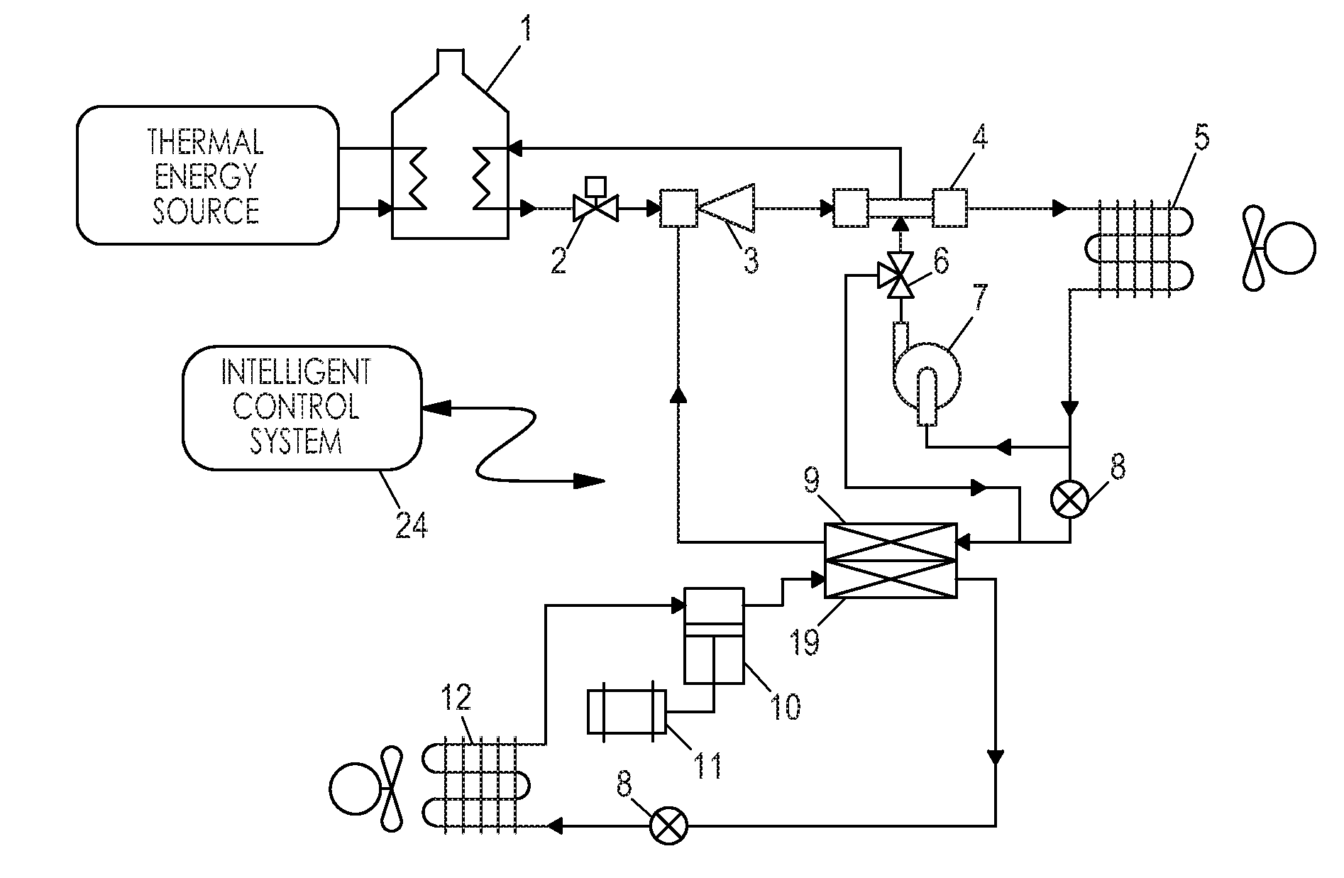
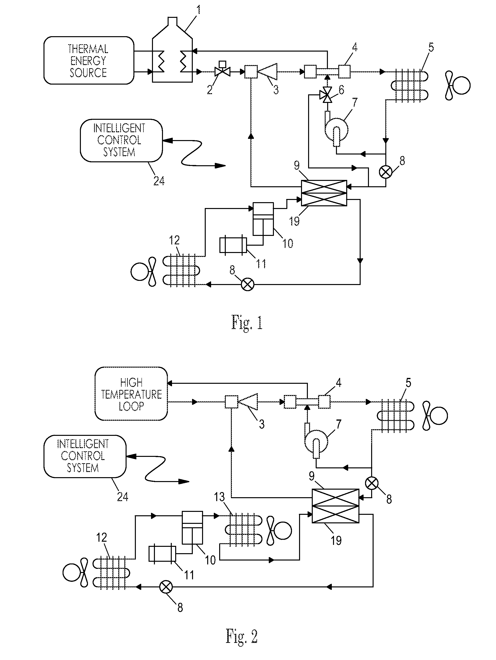
[0058]Unlike the present invention, systems known in the prior art are not cascade systems. Specifically, they do not use an thermally-powered ejector cooling loop to reduce the condensing temperature of a separate mechanically-powered cooling loop. Also, the prior art does not show a cooling system including an ejector cooling loop which further includes a vapor expander which can also function as a mechanical compressor when no external heat source is available. Also, no thermally enhanced system is seen in the prior art which includes an intelligent controller which optimizes the system performance by changing the temperature of the evaporator in an ejector cooling loop to alter the condensing temperature of a mechanical primary cooling loop.

[0059]According to various exemplary embodiments, a thermally enhanced cascade cooling system may use input thermal energy supplied from a variety of different sources. In some embodiments, the thermal energy input reduces the amount of elect...


PUM


Abstract

A cascade cooling system that uses low-grade thermal and other energy input sources to provide refrigeration and air conditioning in stationary and mobile applications. A two-loop embodiment includes a heat-powered first loop incorporating a vapor-jet compressor and a second loop based on a mechanical compressor powered by an electric motor or other source of rotational torque. The system uses waste heat, solar thermal or a fuel-fired heat source to partially or fully offset mechanical / electrical energy input. The system can also operate entirely on thermal, electrical or mechanical input. The ability to use multiple energy sources in any combination maximizes energy efficiency, performance and reliability. The system is well suited to making beneficial use of waste heat in vehicle applications. In stationary applications, solar thermal and / or waste heat from industrial processes can be used to improve the efficiency of conventional cooling systems.

Description

CROSS REFERENCE TO RELATED APPLICATION[0001]This application is a Divisional Patent Application of U.S. patent application Ser. No. 12 / 788,631, filed on May 27, 2010.BACKGROUND[0002]1. Field[0003]This application relates to a cascade cooling system, specifically one incorporating a jet ejector compressor and a mechanical compressor.[0004]2. Prior Art[0005]Air conditioning and refrigeration are among the most energy consuming processes in the developed world. Historically, the terms referred to the application of a colder material, such as ice or water, to absorb heat from a hotter area. Today cooling is more often accomplished using a chemical or mechanical process to forcibly move heat from a colder region to a hotter region. These processes are always energy intensive and become more so as the temperature difference between the colder and hotter areas increase.[0006]Both the need for cooling, and the cost of cooling, increase proportionate to the temperature of the external enviro...

Claims


Application Information

Patent Timeline
Patent Type & Authority Applications(United States)
IPC IPC(8): F25B27/02
CPCF25B27/02B60H1/32F25B1/08F25B7/00Y02A40/966Y02A30/274Y02A40/963
Inventor ALSTON, GERALD ALLEN
Owner ALSTON GERALD ALLEN
Learn More