
Optical detection method and system for detecting a spatial feature on a surface of a substrate

a detection method and optical technology, applied in the direction of material analysis, phase-affecting property measurement, instruments, etc., can solve the problems of affecting the resolution of the image, the inability to reliably scan the mask or the wafer on and the inability to reliably detect the presence of particles or other defects

Inactive Publication Date: 2021-03-11
NEDERLANDSE ORG VOOR TOEGEPAST-NATUURWETENSCHAPPELIJK ONDERZOEK (TNO)
View PDF0 Cites 0 Cited by
  • Summary
  • Abstract
  • Description
  • Claims
  • Application Information

AI Technical Summary

Benefits of technology

The present invention provides an optical detection method that can detect very small spatial features on a surface of a sample. The method uses a reference radiation that has the same spatial phase profile as the optical radiation provided to the sample. The reference radiation can be either a separate reference beam or a portion of the returned radiation that is obtained by using a specular reflected portion of the returned radiation. An amplitude or intensity reducing filter can be used to reduce the intensity of the specular reflected portion. The filtered specular reflected portion is split into two parts using a polarizing beam splitter after the birefringent phase mask. This helps to provide interference in two branches.

Problems solved by technology

Defects and small particle contamination of wafers and masks has always been an issue in lithography systems.
However, currently no measurement tool exists to reliably scan masks or wafers on the presence of particles or other defects that are smaller than 20 nm within in a reasonable amount of time.
However, also dark field imaging has its limitations in what level of detail may still be resolvable.
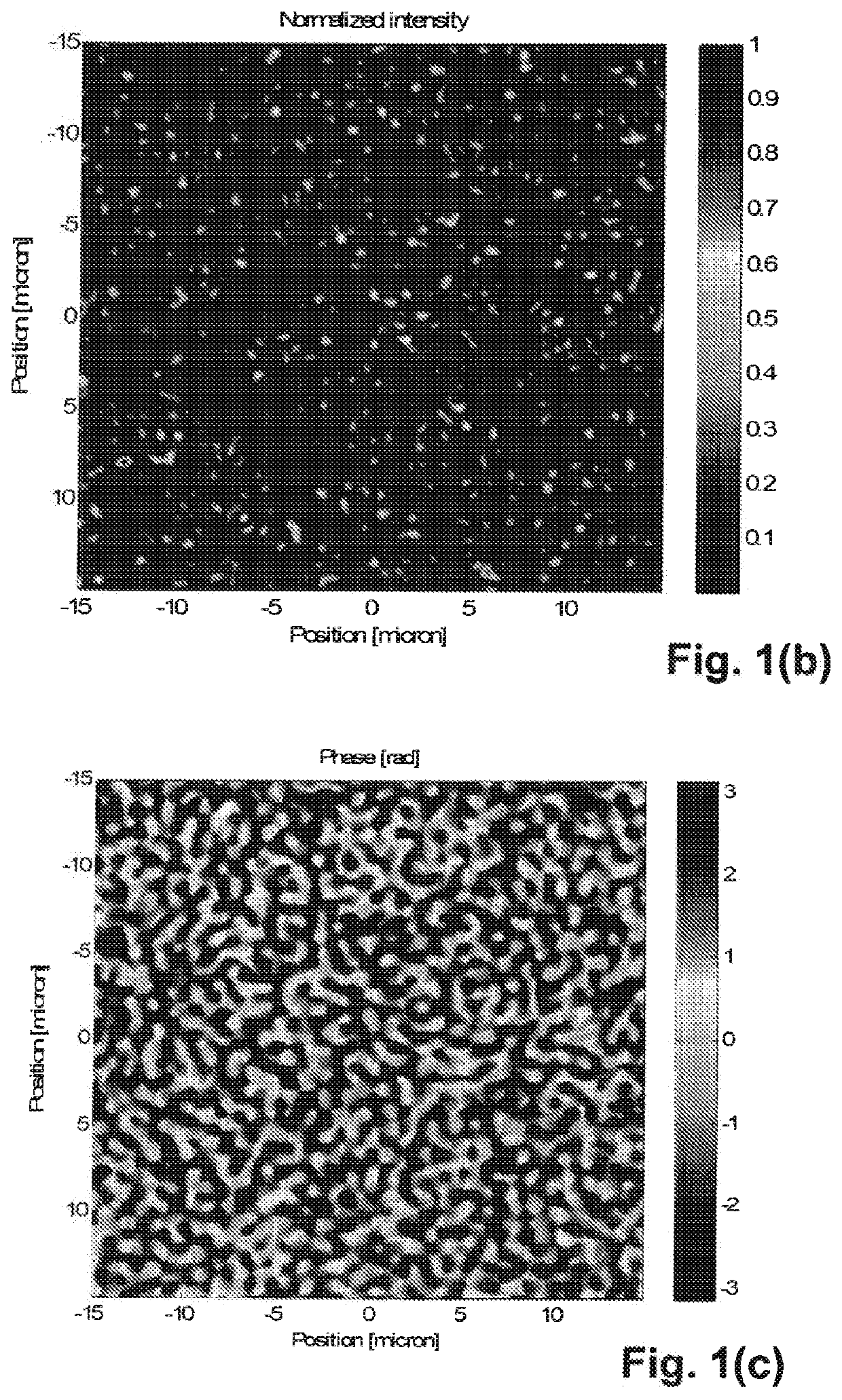
It can be shown that for a very smooth wafer with 0.1 nm surface roughness (rms) dark field imaging techniques result in a particle detection limit that enables to resolve particles that are at least 20 nm.
In other words, particles smaller than this limit cannot be detected using these traditional methods.

Method used


Image

  • Optical detection method and system for detecting a spatial feature on a surface of a substrate
  • Optical detection method and system for detecting a spatial feature on a surface of a substrate
  • Optical detection method and system for detecting a spatial feature on a surface of a substrate

Examples


Embodiment Construction

[0039]The following is a detailed description of the principles and considerations underlying the ideas, concepts and embodiments described herein.

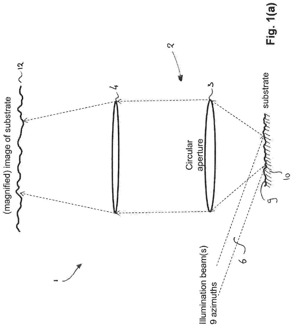
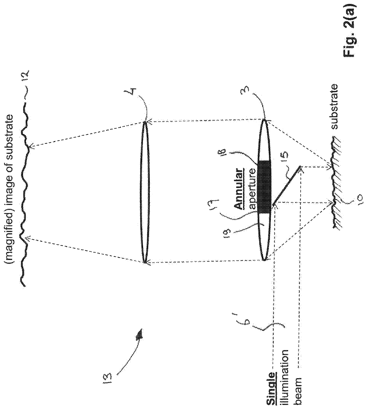
[0040]FIG. 1(a) shows a conceptual drawing of an off-axis illuminated dark field imaging system 1. As illustrated, the system consists primarily of an optical projection arrangement 2, consisting of focusing lenses 3 and 4. A substrate 10 having a surface 9 to be examined, is illuminated with an incident optical beam 6. Optical beam 6 illuminates the surface 9 under a non-straight angle therewith, i.e. under an angle with both the surface itself and the normal (i.e. transverse direction) to the surface. Preferably, as indicated in FIG. 1(a), measurements are taken from a plurality of different azimuths in order to suppress speckle in the image. Hence, the measurement may for example be repeated with the beam 6 incident from different (e.g. nine, as in FIG. 1(a)) azimuthal directions. As may be appreciated, in a different implementation, a...


PUM

PropertyMeasurementUnit
surface roughnessaaaaaaaaaa
angleaaaaaaaaaa

Abstract

This document relates to an optical detection method and system for detecting a spatial feature on or below a surface of a substrate. The method includes providing, using an optical radiation source, a beam of optical radiation; directing the optical radiation beam using beam-directing optics towards the substrate surface for impinging the optical radiation beam on the surface; receiving, by a focusing objective, a returning portion of the optical radiation that is returned by the substrate surface, said returning portion including a scattered portion that is scattered by the substrate; and providing a reference radiation having an equal phase with the returning portion of the optical radiation. The method further comprises combining a first part of the reference radiation with a first part of the scattered portion for forming a first interference pattern in a first imaging plane, and combining a second part of the reference radiation with a second part of the scattered portion for forming a second interference pattern in a second imaging plane; and prior to said combining, using an optical filter, adding a phase difference to at least one of the second part of the reference radiation or the second part of the scattered portion, for inverting the phase of said at least one of the second part of the reference radiation or the second part of the scattered portion.

Description

FIELD OF THE INVENTION[0001]The present invention is directed at an optical detection method for detecting a spatial feature on a surface of a substrate, the method including: providing, using an optical radiation source, a beam of optical radiation; directing the optical radiation beam using beam-directing optics towards the substrate surface for impinging the optical radiation beam on the surface; receiving, by a focusing objective, a returning portion of the optical radiation that is returned by the substrate surface; and providing a reference radiation. The invention is further directed at an optical detection system for detecting a spatial feature on a surface of a substrate.BACKGROUND[0002]The present document relates to optical detection of very small structures on a smooth surface, e.g. surface defects or particle contaminations on the surface of a substrate. Defects and small particle contamination of wafers and masks has always been an issue in lithography systems. With th...

Claims


Application Information

Patent Timeline
Patent Type & Authority Applications(United States)
IPC IPC(8): G01N21/45G01N21/95G01N21/88
CPCG01N21/45G01N21/9505G01N2201/0638G01N2021/8848G01N2201/0633G01N21/8806G01N21/9501G01N2021/95676
Inventor KOEK, WOUTER D.VAN ZWET, ERWIN JOHN
Owner NEDERLANDSE ORG VOOR TOEGEPAST-NATUURWETENSCHAPPELIJK ONDERZOEK (TNO)
Learn More