Adjustable division plate for classifier coal flow control

a technology of flow control and division plate, which is applied in the field of conveying systems, can solve the problems that coal pipes also negatively affect combustion efficiency, and achieve the effects of improving coal particle distribution, preventing reverse air flow, and improving coal particle distribution

Active Publication Date: 2015-02-26
BABCOCK POWER SERVICES
View PDF23 Cites 16 Cited by
  • Summary
  • Abstract
  • Description
  • Claims
  • Application Information

AI Technical Summary

Benefits of technology

[0009]In certain embodiments, the solid particle flow distribution controller can also include a coal classifier having an inlet and a discharge skirt having a plurality of outlets. The division plates can be mounted within the interior of the discharge skirt proximate an upstream portion of the plurality of outlets. The extension plates can be radially inward of the discharge skirt. The discharge skirt can also have an interior divided into a plurality of circumferentially segmented chambers by the division plates mounted within the discharge skirt for dividing flow from the inlet to a plurality of outlet pipes downstream of the coal classifier. The extension plates can be configured to move in the upstream and downstream direction independent of one another to extend upstream of their respective division plates as needed to improve coal particle distribution between the outlets and chambers of the discharge skirt. A feed pipe can extend through the coal classifier along a centerline thereof. A center pipe can be mounted within the classifier for control of an adjustable return baffle for prevention of reverse air flow through the classifier or re-entrainment of coarse particles.
[0010]The invention also provides a method of controlling solid particle flow in each pipe of a solid particle piping system. The method includes adjusting one or more of the positions of the extension plates of a solid particle flow distribution controller as described above to change so

Problems solved by technology

Imbalanced coal flow between coal pipes also negatively impacts combustion efficiency, as indicated by unburned carbon (UBC), heat rate, heat balance etc., as well as gaseous emissions such as NOX, CO, etc.
Orifices (fixed or variable) installed in

Method used


Image

  • Adjustable division plate for classifier coal flow control
  • Adjustable division plate for classifier coal flow control
  • Adjustable division plate for classifier coal flow control

Examples


Embodiment Construction

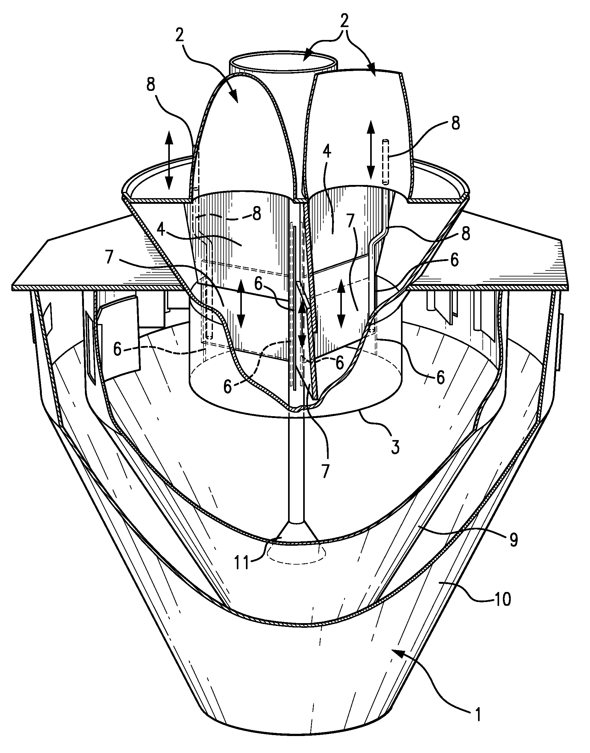
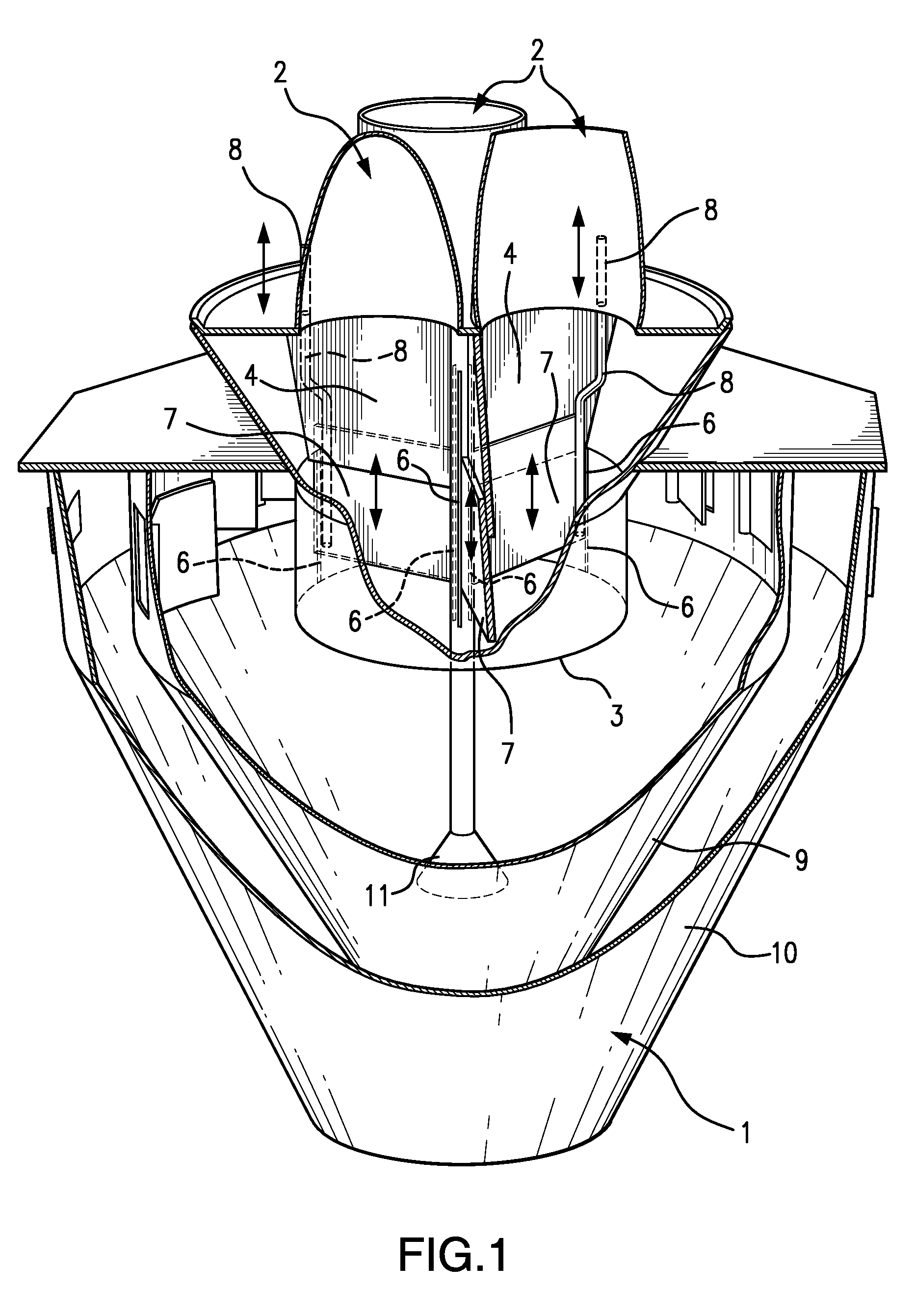
[0018]Reference will now be made to the drawings wherein like reference numerals identify similar structural features or aspects of the subject invention. For purposes of explanation and illustration, and not limitation, a partial view of an exemplary embodiment of a classifier in accordance with the invention is shown in FIG. 1 and is designated generally by reference character 1. Other embodiments of classifiers in accordance with the invention, or aspects thereof, are provided in FIGS. 2-3, as will be described. The systems and methods of the invention can be used, for example, on centrifugal type static classifiers to correct coal flow distribution with little or no negative impact on PA (primary air) flow distribution.

[0019]Classifier 1 provides for solid particle separation and flow correction in a solid particle conveyance system. Classifier 1 is shown by way of example as a coal particle classifier for classification of coal particles by removal of oversized particles and di...


PUM

PropertyMeasurementUnit
Temperatureaaaaaaaaaa
Flow rateaaaaaaaaaa
Distributionaaaaaaaaaa

Abstract

A solid particle distribution controller includes a plurality of division plates proximate a division between an upstream solid particle conveyance pipe and a plurality of downstream pipes. The solid particle distribution controller also includes a plurality of extension plates. Each of the extension plates is movably mounted proximate to a respective division plate for movement in an upstream and downstream direction with respect to the division plate. The plurality of extension plates are configured and adapted for motion in the upstream and downstream direction independent of one another to extend upstream of the division plates as needed to improve solid particle distribution among the downstream pipes.

Description

CROSS-REFERENCE TO RELATED APPLICATIONS[0001]This application claims priority to U.S. Provisional Patent Application No. 61 / 586,197 filed Jan. 13, 2012, which is incorporated by reference herein in its entirety.BACKGROUND OF THE INVENTION[0002]1. Field of the Invention[0003]The present invention relates to systems for conveying solid particles through gas flows, and more particularly to coal pulverizer (mill) discharge piping systems wherein coal particles are conveyed through air flows.[0004]2. Description of Related Art[0005]In coal combustion systems, coal and primary air (PA) flow distribution between burner lines is important for optimizing combustion and burner performance. Low NOX burner design usually requires that coal mass flow imbalance between coal pipes should be within + / −15% deviation from the mean value, or lower, to ensure burner performance. Imbalanced coal flow between coal pipes also negatively impacts combustion efficiency, as indicated by unburned carbon (UBC),...

Claims


Application Information

Patent Timeline
IPC IPC(8): F23K3/02B65G53/52B65G53/04
CPCF23K3/02B65G53/04B65G53/528F23K2203/104F23K2203/006F23K2203/201F23K2203/105F23K2201/30F23K2201/10Y10T29/49716
Inventor RATH, JOHNYALDIZLI, MURAT
Owner BABCOCK POWER SERVICES
Why Eureka
Try Eureka