Lift system, overload coupling and method for operating the lift system

Active Publication Date: 2015-03-05
EFS FUR HEBE UND HANDHABUNGSTECHN MBH
View PDF1 Cites 3 Cited by
  • Summary
  • Abstract
  • Description
  • Claims
  • Application Information

AI Technical Summary

Benefits of technology

[0007]It is an object of the invention to provide a lift system of the kind described above configured in such

Problems solved by technology

If this fixed rotational angle assignment is lost, the complex calibration process described above has to be performed again, which is very work-intensive and time-consuming.
Direct consequences of this are frequent gear assembly damage which requires this component to be replaced.
Such collisions occur frequently, in particular, in the case of putting into service, in the setting-up operation, in the case of fault messages or in the case of control faults.
However, a reasonable configuration of the limiting torque or slipping torque is dif

Method used


Image

  • Lift system, overload coupling and method for operating the lift system
  • Lift system, overload coupling and method for operating the lift system
  • Lift system, overload coupling and method for operating the lift system

Examples


Example

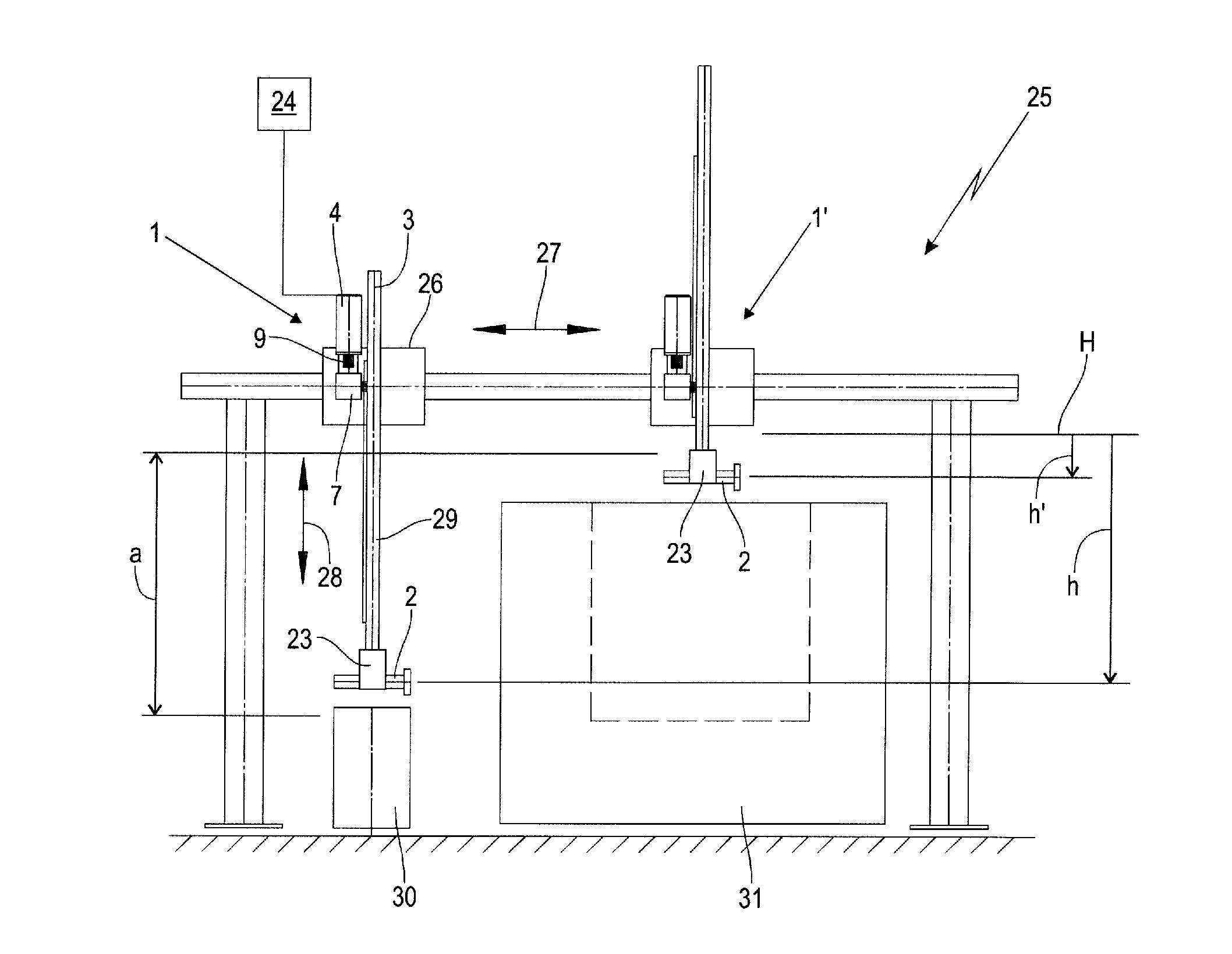
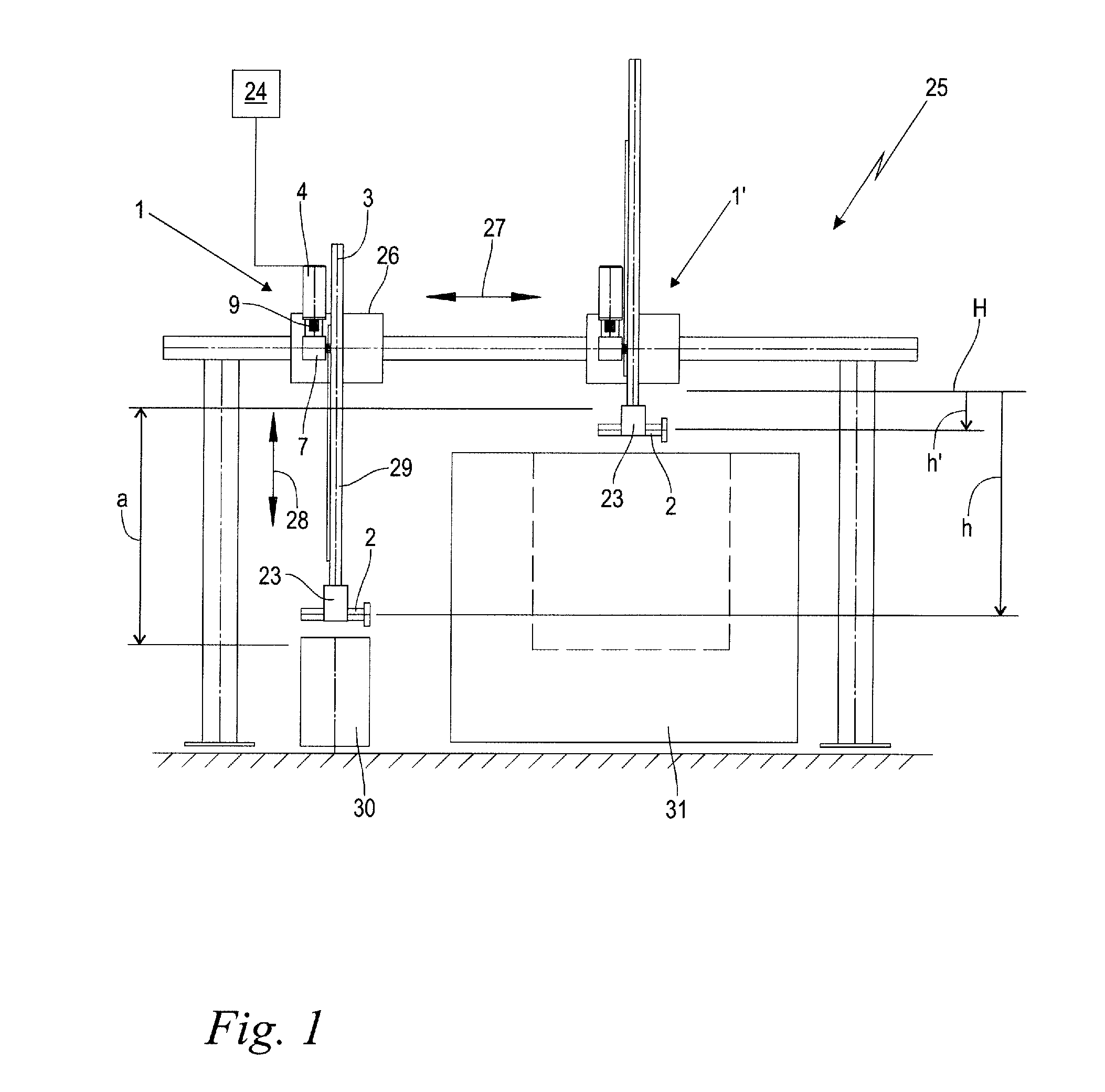
[0028]FIG. 1 shows a handling system 25 for objects 2 in a schematic side view. The handling system 25 is equipped here, for example, in a two-axial fashion with a horizontal adjustment device 26 for moving the object 2 in a horizontal direction according to a double arrow 27, and with a vertical lift system 1 for lifting and lowering the object 2 in the direction of a vertical hoist axis 3 according to a double arrow 28. Any desired number of movement axes can be provided as long as at least the vertical lift system 1 is present.

[0029]The handling system 25 which is shown by way of example is constructed in the form of a gantry which spans a feed belt 30 and a processing machine 31 for the objects 2. The lift system 1 is provided with a holding unit 23 for picking up and holding an object 2.

[0030]The object 2, which is transported by the feed belt 30, is grasped by the holding unit 23, lifted up in the vertical direction by the lift system 1 counter to the acting gravity, moved to ...


PUM


Abstract

A lift system defines a vertical hoist axis and includes a holding unit for lifting and lowering an object in a direction along the vertical hoist axis. An overload coupling mutually connects the drive shaft of a motor and the input shaft of a gear assembly. The overload coupling includes a latch mechanism having a motor latch part and a gear assembly latch part. The latch mechanism defines a latch characteristic providing a first transmittable torque in a lowering rotational direction and a second transmittable torque in a lifting rotational direction determined so as to cause the first transmittable torque to be less than the second transmittable torque. The latch mechanism includes a rotational positioning device configured to permit a latching of the motor latch part into the gear assembly latch part in only one possible relative rotational angle position within 360° referred to the lifting rotational direction.

Description

CROSS REFERENCE TO RELATED APPLICATION[0001]This application claims priority of European patent application no. 13004334.2, filed Sep. 4, 2013, the entire content of which is incorporated herein by reference.BACKGROUND OF THE INVENTION[0002]In handling technology, objects are moved from one location to another by means of a handling system in order to transfer them, for example, from a feed belt to a processing machine. Such handling systems have both a horizontal movement device and a vertically operating lift system with a holding unit for lifting and lowering an object in the direction of a vertical hoist axis. The lift system comprises a motor unit with a drive shaft, a rotational angle transducer for the drive shaft and a gear assembly with an input shaft, wherein the motor unit drives the input shaft of the gear assembly with its drive shaft.[0003]The specific motor unit generally comprise a servomotor whose rotational speed can be regulated in order to permit defined vertical...

Claims


Application Information

Patent Timeline
IPC IPC(8): F16H19/02F16H35/10
CPCF16H35/10F16H19/02B66D1/14F16D7/044F16D43/2024Y10T74/188
Inventor PERABO, KLAUS
Owner EFS FUR HEBE UND HANDHABUNGSTECHN MBH
Why Eureka
Try Eureka