System and method for estimating and controlling temperature of engine component

a technology of engine components and temperature, applied in the direction of electric control, machine/engine, fuel injection control, etc., can solve the problems of premature valve failure, overheating of engine components, and failure to consider the temperature of the valve,

Active Publication Date: 2015-03-05
CATERPILLAR INC
View PDF5 Cites 12 Cited by
  • Summary
  • Abstract
  • Description
  • Claims
  • Application Information

AI Technical Summary

Benefits of technology

[0005]In one aspect, an engine system is disclosed. The engine system includes an ambient air pressure sensor configured to generate a signal indicative of a pressure of ambient air. The engine system also includes an operational parameter sensor configured to generate a signal indicative of one or more operational parameters associated with the engine. The engine system further includes a controller communicably coupled to the ambient air pressure sensor and the operational parameter sensor. The controller is configured to receive the signal indicative of the pressure of ambient air and the signal indicative of the one or more operational parameters associated with the engine. The controller estimates the temperature of at least one of ...

Problems solved by technology

This may cause overheating of engine components, such as, for example valves, pistons, and other in-cylinder components associated with the engine.
Overheating may in turn lead to premature failure of the valve.
Such strategies fail to consider a temperature of the valve, a piston, a liner, a cylinder head, and a pre-chamber, which in some situations may ...

Method used


Image

  • System and method for estimating and controlling temperature of engine component
  • System and method for estimating and controlling temperature of engine component
  • System and method for estimating and controlling temperature of engine component

Examples


Embodiment Construction

[0010]Reference will now be made in detail to specific embodiments or features, examples of which are illustrated in the accompanying drawings. Generally, corresponding or similar reference numbers will be used, when possible, throughout the drawings to refer to the same or corresponding parts.

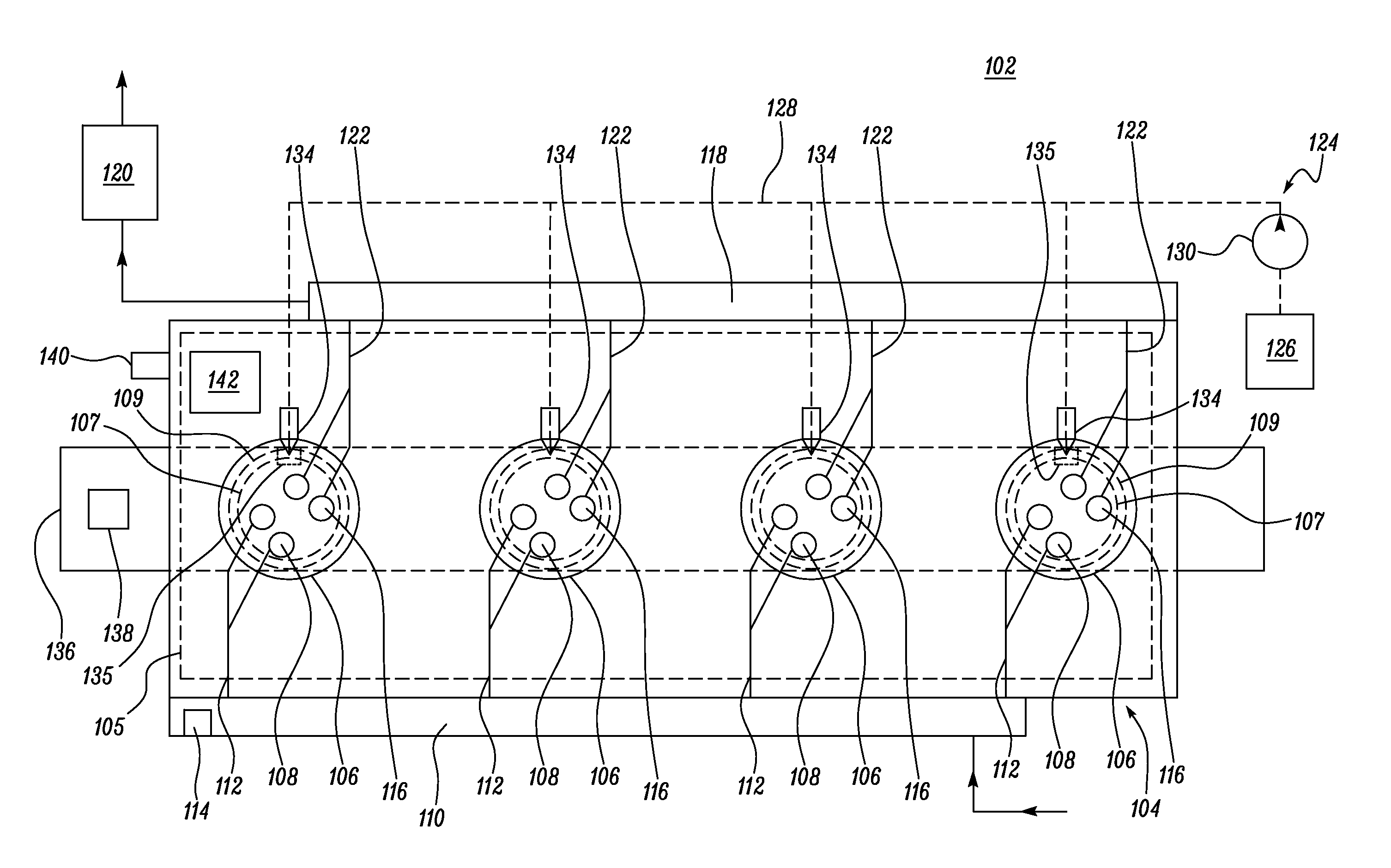
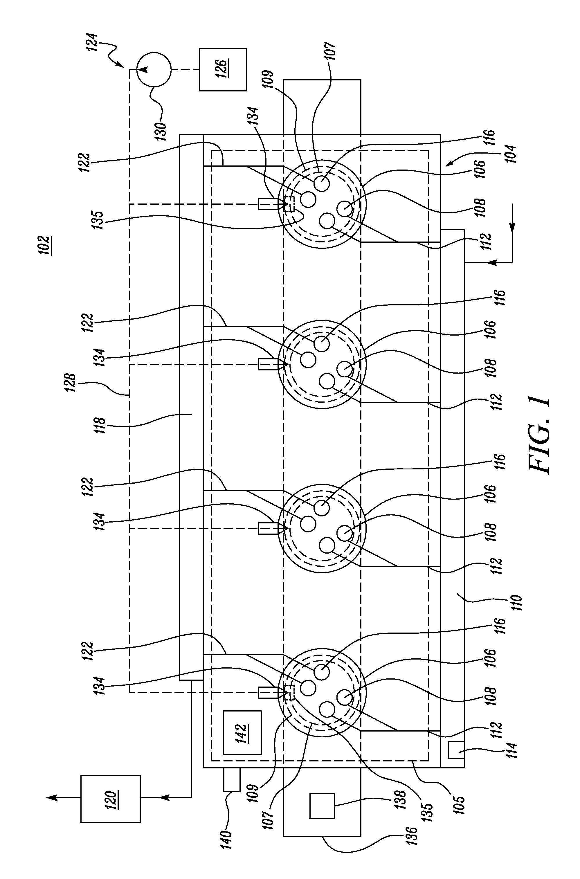
[0011]Referring to FIG. 1, a block diagram of an exemplary engine 102 is illustrated. In one embodiment, the engine 102 may include a compression ignition engine configured to combust a mixture of air and diesel fuel. In alternative embodiments, the engine 102 may include a spark ignition engine such as a natural gas engine, a gasoline engine, or any multi-cylinder reciprocating internal combustion engine known in the art. The engine 102 includes an engine block 104 and a cylinder head 105. The engine block 104 includes a plurality of cylinders 106. Each of the plurality of cylinders 106 includes a piston 107 and a liner 109 disposed within the cylinder 106. Although four cylinders 106 are sho...


PUM


Abstract

An engine system is provided. The engine system includes an ambient air pressure sensor configured to generate a signal indicative of a pressure of ambient air. The engine system also includes an operational parameter sensor configured to generate a signal indicative of one or more operational parameters associated with the engine. The engine system further includes a controller communicably coupled to the ambient air pressure sensor and the operational parameter sensor. The controller is configured to receive the signal indicative of the pressure of ambient air and the signal indicative of the one or more operational parameters associated with the engine. The controller estimates the temperature of at least one of a valve, a piston, a liner, a cylinder head, and a pre-chamber of the engine as a function of the received signals and parameters associated with fuel delivery in a single fuel cycle of the engine.

Description

TECHNICAL FIELD[0001]The present disclosure relates to a system and method for estimating and controlling a temperature of an engine component, and more specifically for the estimation and control of the temperature of a valve, a piston, a liner, a cylinder head, and a pre-chamber associated with an engine.BACKGROUND[0002]For a given configuration, an Internal Combustion Engine (ICE) operating at a higher altitude tends to reach higher temperatures as compared to the engine operating at a lower altitude when producing a same amount of power. This may cause overheating of engine components, such as, for example valves, pistons, and other in-cylinder components associated with the engine. Overheating may in turn lead to premature failure of the valve. In order to prevent overheating, the engine is derated by reducing a fuel supply to the engine. Typical calibration strategies consider constraints such as exhaust gas temperature, peak cylinder pressure, turbocharger speed, compressor o...

Claims


Application Information

Patent Timeline
IPC IPC(8): F02D41/30
CPCF02D41/30F02D41/38F02D41/22F02D2200/022
Inventor HERGART, CARL A.RASMUSSEN, JASON J.
Owner CATERPILLAR INC
Why Eureka
Try Eureka