Apparatus and method to provide breathing support

a technology applied in the field of apparatus and breathing support, can solve the problems of inability to set and vary the user's breathing, devices are generally expensive and out of the reach of a large portion of the population, and devices require substantial training and expertise to operate and maintain

Active Publication Date: 2015-03-05
EUPNEA TECH
View PDF6 Cites 4 Cited by
  • Summary
  • Abstract
  • Description
  • Claims
  • Application Information

AI Technical Summary

Benefits of technology

[0006]It is generally known in the medical profession that stabilization of lung volumes and improvement in gas exchange in patients receiving ventilation assistance could be achieved through appropriate settings and control of the positive pressures generated, amplitude and frequency of oscillating positive pressure in the ventilator. Embodiments described herein provide the user a device and method to set pressures, oscillations, amplitude and frequency, and further allows the user to set the upper limit of positive pressure that is specific for a patient to reduce the likelihood of damage to the lungs. Additionally, the embodiments described herein maintain a patient's mean airway pressure at controlled levels. Device parameters such as levels of fluid in the containers, lengths of the ducts immersed in the fluids in the containers can be varied to control the high as well as low pressures. These embodiments also have features that allow a user to select and modulate breaths per minute, inspiratory time, and the ratio of inspiratory to expiratory time. The embodiments described herein are useful to adults, children and newborn babies. Further, the embodiments can be used during transport of patients, and may be used in facilities that do not have access to mechanical ventilators. Several embodiments described herein can also be converted to a bubble Continuous Positive Airway Pressure (CPAP) system.
[0007]In one embodiment, a ventilator system is provided having a pressurized gas supply, two containers filled with fluid, and a primary duct with two ends—the proximal end and the distal end. The proximal end is connected to the pressurized gas supply. The primary duct is adapted for connection to a patient interface between the proximal and distal ends. At the distal end, a peak inspiratory pressure control duct is connected and immersed in a body of fluid in the first container. A positive end-expiratory pressure control duct is also connected to the distal end of the duct and immersed in the body of fluid in the second container. A two-port valve, also known as a two-way valve, is connected in between the inspiratory pressure control duct and the positive end-expiratory pressure control duct wherein the rate of opening and closing of the valve can be controlled. In addition, at least one safety duct is connected to the primary duct near the proximal end and is immersed in the fluid column in the first container at depth greater than the immersed length of the peak inspiratory pressure control duct Immersed length is the vertical distance measured from the top of the fluid surface to the tip of a pressure control duct. The depth to which the at least one safety duct is immersed is controlled by the user. In some embodiments, ducts have simple markings, for example in cm of water, to help the user set high pressure (peak inspiratory pressure), low pressure (positive end-expiratory pressure), and high-pressure limit (Pop-Off). In other embodiments, the immersed length is adjusted by varying water column heights or by varying positions of ducts or both to deliver high and low pressures. In certain embodiments, as a safety feature, the default position of the ventilator system is to deliver the lower pressure at all times as CPAP when the ventilator system is connected to the patient.
[0008]The use of double containers allows the user to isolate and fix any issues with one container or duct without disconnecting the patient from the breathing support. Also, the use of double containers prevents the bubbles generated in one container from impacting the liquid column level and pressure in the duct placed in the other container. In some embodiments, two-way or three-way valve allows the user to set breathing rates from 4-60 per minute, known as conventional mechanical breaths, and frequencies in the range of 60-900 per minute, known as high frequency range. In other embodiments, a controller allows the user to control inspiratory to expiratory ratios or have it fixed as percent of cycle time to maintain a desired inspiration time to expiration time ratio, when the cycle frequencies are adjusted. Valves used in the embodiments include without limitation solenoid valves, pneumatic valves and solar powered valves.
[0010]In yet another embodiment, a second valve is also provided wherein the second valve is an open-shut type shutoff valve which can isolate the positive end-expiratory pressure control duct from the remainder of the ventilator gas flow circuit.

Problems solved by technology

These devices are generally expensive and out of reach of a large portion of the population, particularly in economically disadvantaged countries.
These devices also require substantial training and expertise to operate and maintain.
Further, these devices do not provide the user the ability to set and vary upper limit of safe positive pressure that is patient specific and commensurate with the peak inspiratory pressure levels set during ventilation in an easy and less expensive way using a fluid column.
Further, when two pressure control conduits are located in the same container, the interaction between the two conduits in operation may impact pressures at a patient interface.

Method used


Image

  • Apparatus and method to provide breathing support
  • Apparatus and method to provide breathing support
  • Apparatus and method to provide breathing support

Examples


example 1

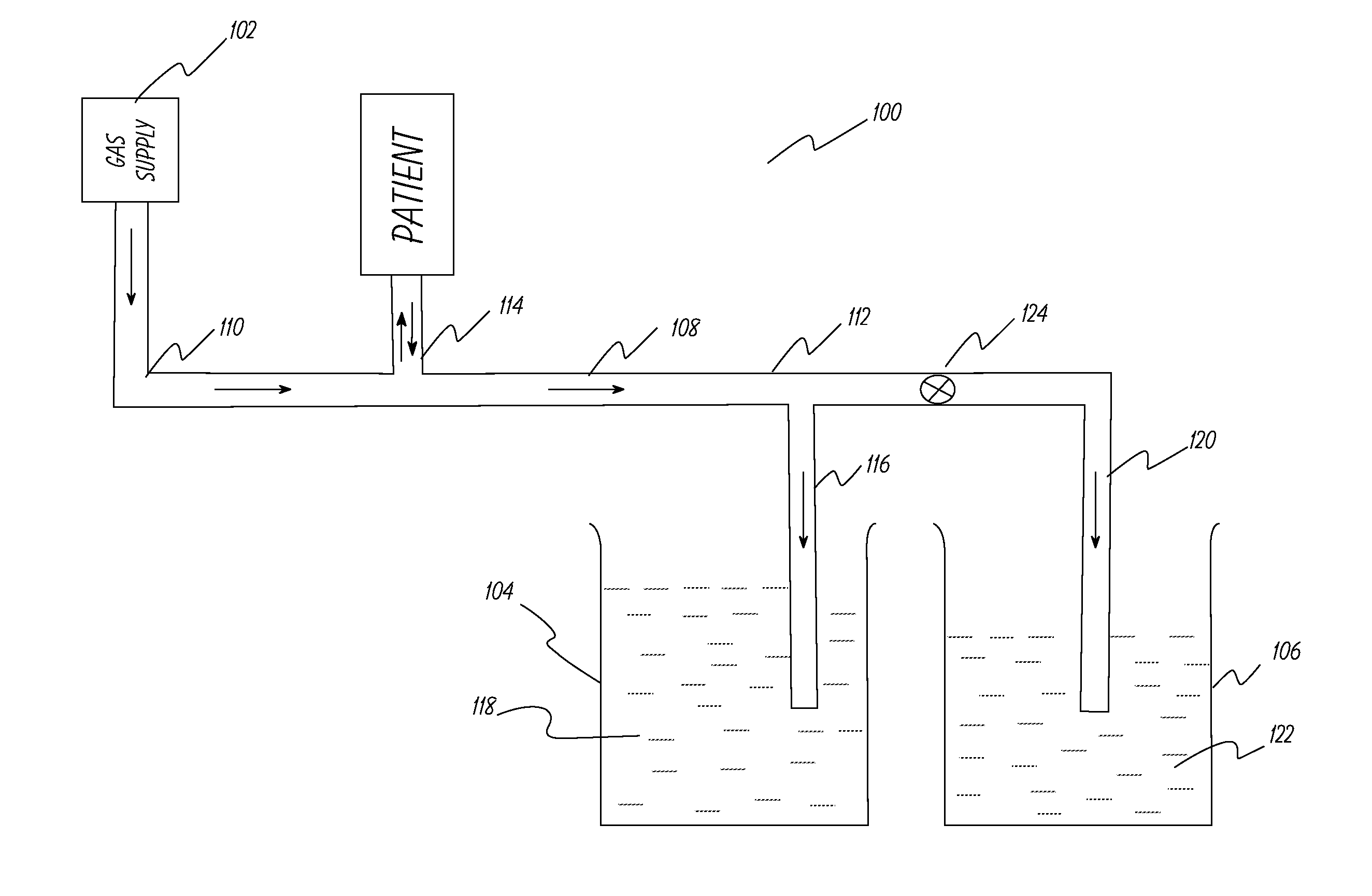
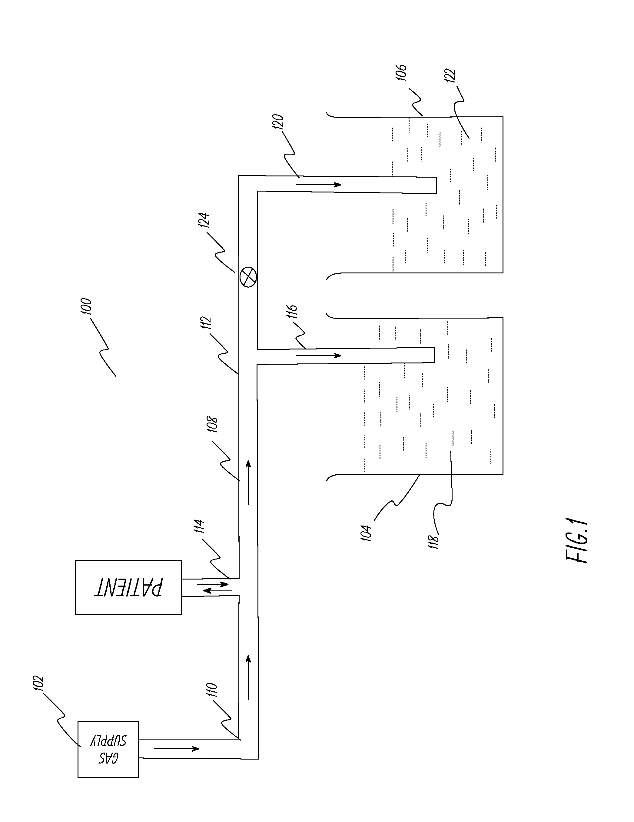
[0053]This example describes the ventilator system used and experiments performed to test the system described in FIG. 1. A lung machine manufactured by Ingmar Medical, Pittsburgh, Pa. (www.ingmarmed.com) was connected at patient interface of the ventilator system. A two-port (two-way) solenoid valve manufactured by MAC Valves, Inc., Wixom, Mich. (www.macvalves.com) was used in the system. The open-shut cycle of the valve was controlled using an electronic timer made by IDEC Corporation, Sunnyvale, Calif. (us.idec.com). Compressed air and air / oxygen mixtures were used in the tests. The tubing used was the standard 10 mm tubing used with conventional ventilator systems in a hospital setting. The fluid in the containers was water at room temperature. The pressure at the patient interface was measured using a manometer manufactured by Life Design Systems, Inc., Madison, Wis. The manometer had a range of −20 cm water to +80 cm water in increments of 1 cm water. Tests were run for gas fl...

example 2

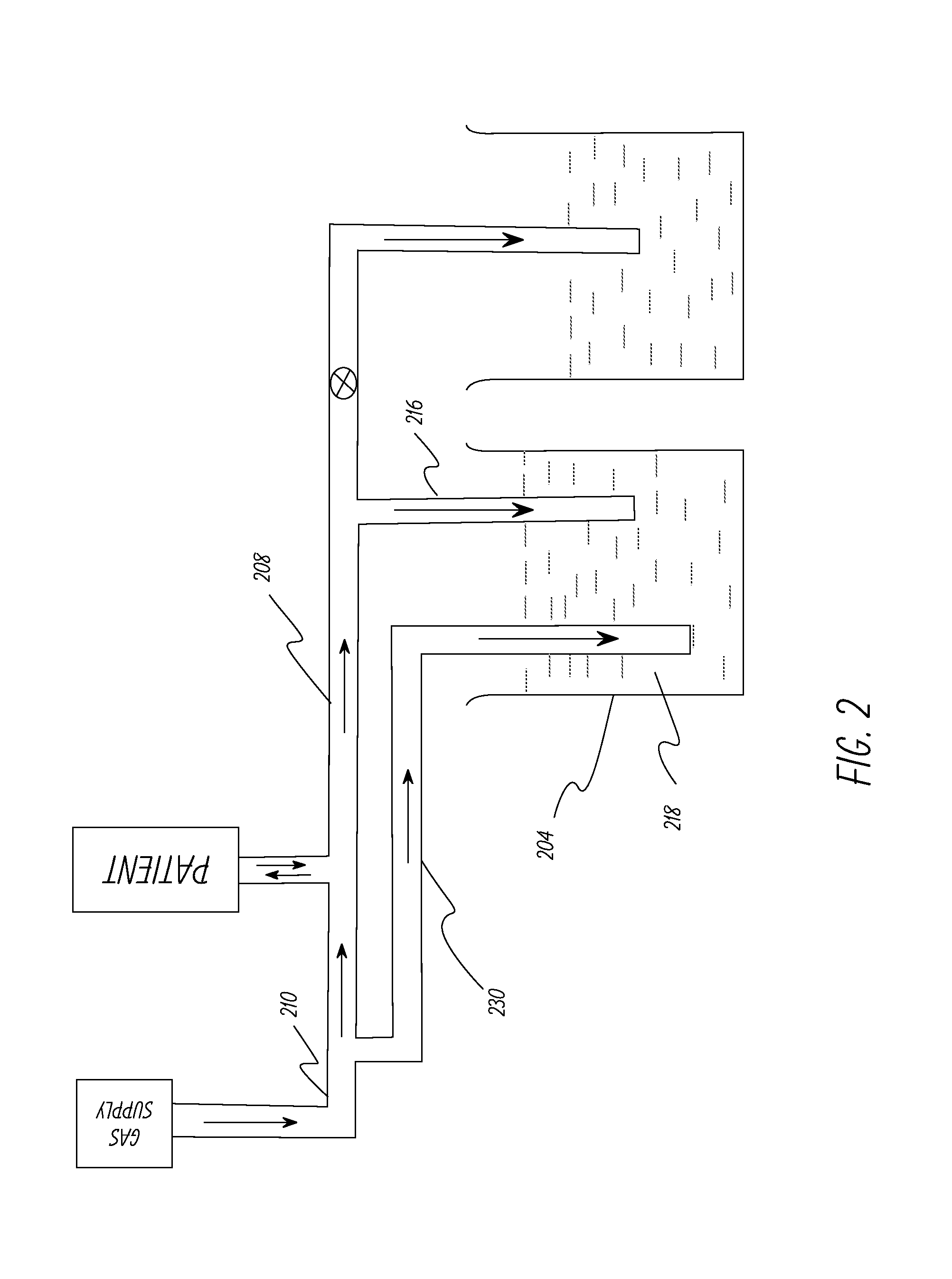
[0056]The system in Example 1 was modified to include a safety duct as shown in FIG. 2. The safety duct was set at a pressure 3 cm of water above the PIP pressure. The primary duct was intentionally squeezed at the distal end to simulate occlusion of the duct and the safety duct released the pressure buildup when the pressure at the patient interface reached 3 cm of water above the PIP pressure. The tests were repeated successfully at different pressure levels.

example 3

[0057]This example describes the ventilator system used and experiments performed to test the system described in FIG. 5. A lung machine manufactured by Ingmar Medical, Pittsburgh, Pa. (www.ingmarmed.com) was connected at patient interface of the ventilator system. A three-port (three-way) solenoid valve manufactured by MAC Valves, Inc., Wixom, Mich. (www.macvalves.com) was used in the system. The size of the three-port valve was the same as the two-port (two-way) valve used in Example 1. The cycling of the valve was controlled using an electronic timer made by IDEC Corporation, Sunnyvale, Calif. (us.idec.com). Compressed air and air / oxygen mixtures were used in the tests. The tubing used was the standard 10 mm plastic tubing used with conventional ventilator systems in a hospital setting. The fluids in the containers were water at room temperature. The pressure at the patient interface was measured using a manometer manufactured by Life Design Systems, Inc., Madison, Wis. The manom...


PUM


Abstract

A ventilator, or a breathing assistance apparatus, is disclosed to ventilate patients who may have breathing difficulties, said device comprising a inspiratory pressure control duct configured to be immersed in a first body of fluid; a positive end-expiratory pressure control duct configured to be immersed in a second body of fluid; at least one valve connected to the peak inspiratory pressure control duct and to the positive end-expiratory pressure control duct, and at least one controller communicably connected to the valve to control rate of cycling of the valve, thereby controlling number of breaths per minute, and to control the duration of peak inspiratory pressure also known as inspiratory time.

Description

CROSS-REFERENCE TO RELATED APPLICATIONS[0001]This application claims the benefit of the earlier filing dates of co-pending U.S. Provisional Patent Application No. 61 / 874,323, filed Sep. 5, 2013; U.S. Provisional Patent Application No. 61 / 929,947, filed Jan. 21, 2014; and these provisional patent applications are incorporated herein by reference.FIELD[0002]Embodiments described herein concern devices and methods that assist gas exchange and stabilize lung volume in patients of all ages with breathing problems.BACKGROUND[0003]Patients who have breathing difficulties are conventionally provided breathing assistance using mechanical ventilators. These devices are generally expensive and out of reach of a large portion of the population, particularly in economically disadvantaged countries. These devices also require substantial training and expertise to operate and maintain. Further, these devices do not provide the user the ability to set and vary upper limit of safe positive pressure ...

Claims


Application Information

Patent Timeline
Patent Type & Authority Applications(United States)
IPC IPC(8): A61M16/20A61M16/00
CPCA61M16/0057A61M16/201A61M16/1045A61M2205/3348A61M16/0096A61M2016/0039A61M16/204A61M16/205A61M16/202A61M16/0666A61M16/0875A61M2205/3334
Inventor SARDESAI, RAJENDRA GURUDASRAMANATHAN, RANGASAMY
Owner EUPNEA TECH
Why Eureka
Try Eureka