Decorative substrate and touch panel

a technology of decorative substrates and touch panels, applied in the direction of pulse techniques, instruments, transportation and packaging, etc., can solve the problems of poor appearance, damage to devices, white borders, black borders or white spots, etc., and achieve the effect of improving the performance of devices and poor appearan

Inactive Publication Date: 2015-03-05
WINTEK CORP
View PDF0 Cites 6 Cited by
  • Summary
  • Abstract
  • Description
  • Claims
  • Application Information

AI Technical Summary

Benefits of technology

[0008]The invention is further directed to a touch panel capable of providing both ideal strength and ideal appearance.
[0029]Based on above, because the decorative substrate and the touch panel of the invention are respectively provided with the protective layer disposed in edge regions adjacent to the sidewalls of the substrate, the side etching of the acid solution (e.g., hydrofluoric acid, hydrochloric acid and so on) during the strengthening process for the substrate can be blocked. Accordingly, devices around the edge regions of the substrate can be protected from corrosion by the acid solution (e.g., hydrofluoric acid, hydrochloric acid and so on), such that the problems of poor appearance can be effectively solved. Moreover, performance of the devices can also be improved.

Problems solved by technology

However, after the etching-resistant film is attached, a side etching of an acid solution (e.g., hydrofluoric acid, hydrochloric acid and so on) on the edges of the substrate are prone to extend inwardly during the second strengthening process, resulting in problems of poor appearance such as white borders, black borders or white spots, and even damages and malfunctions to devices.

Method used


Image

  • Decorative substrate and touch panel
  • Decorative substrate and touch panel
  • Decorative substrate and touch panel

Examples


first embodiment

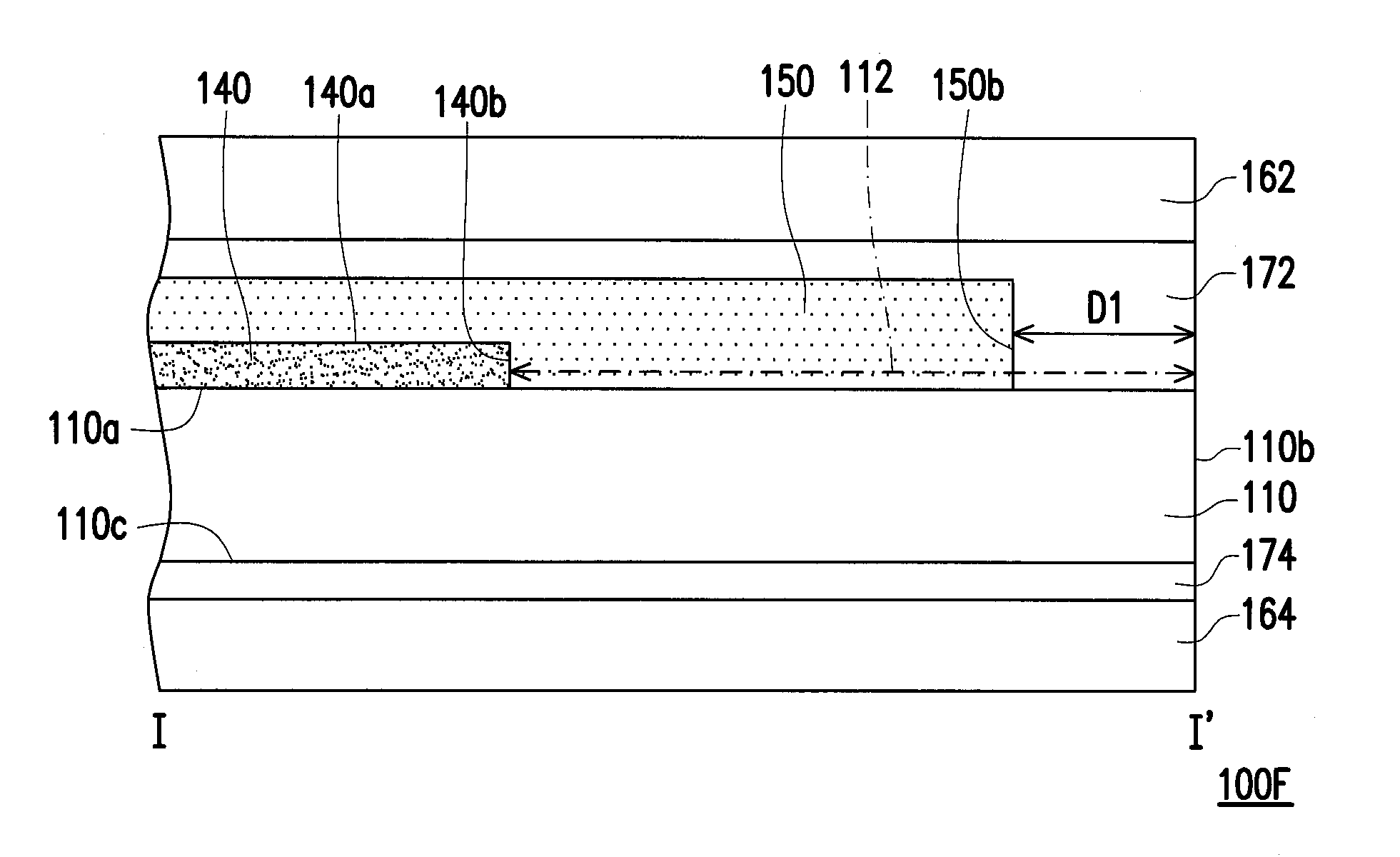
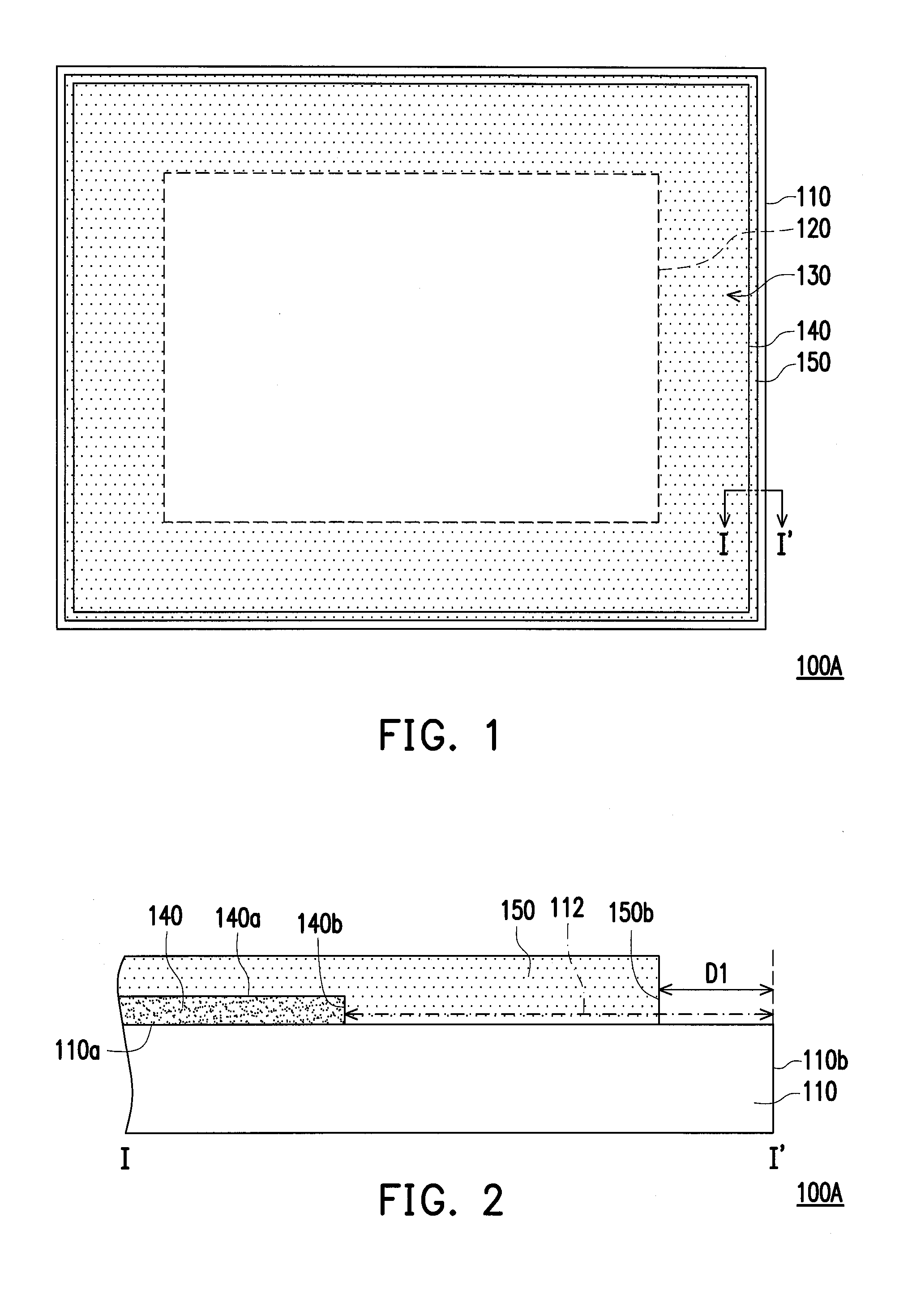
[0042]FIG. 1 is a schematic top view of a decorative substrate 100A according to the invention, and FIG. 2 is a cross-sectional view illustrating the decorative substrate 100A depicted in FIG. 1 along line I-I′.

[0043]Referring to FIG. 1 and FIG. 2 together, the decorative substrate 100A has a first region 120 and a second region 130, and the second region 130 surrounds the first region 120. However, the invention is not limited thereto. In other embodiments, the second region 130 can also at least partially surround the first region 120. The decorative substrate 100A includes a substrate 110, a decorative layer 140 and a protective layer 150.

[0044]The substrate 110 has a first surface 110a and a first sidewall 110b. Electrodes, wires or other devices can be selectively formed on the substrate 110, but the invention is not limited to said elements. A material of the substrate 110 includes, for example, glass, quartz, an organic polymer (polymeric compound material) or metal, etc.

[004...

second embodiment

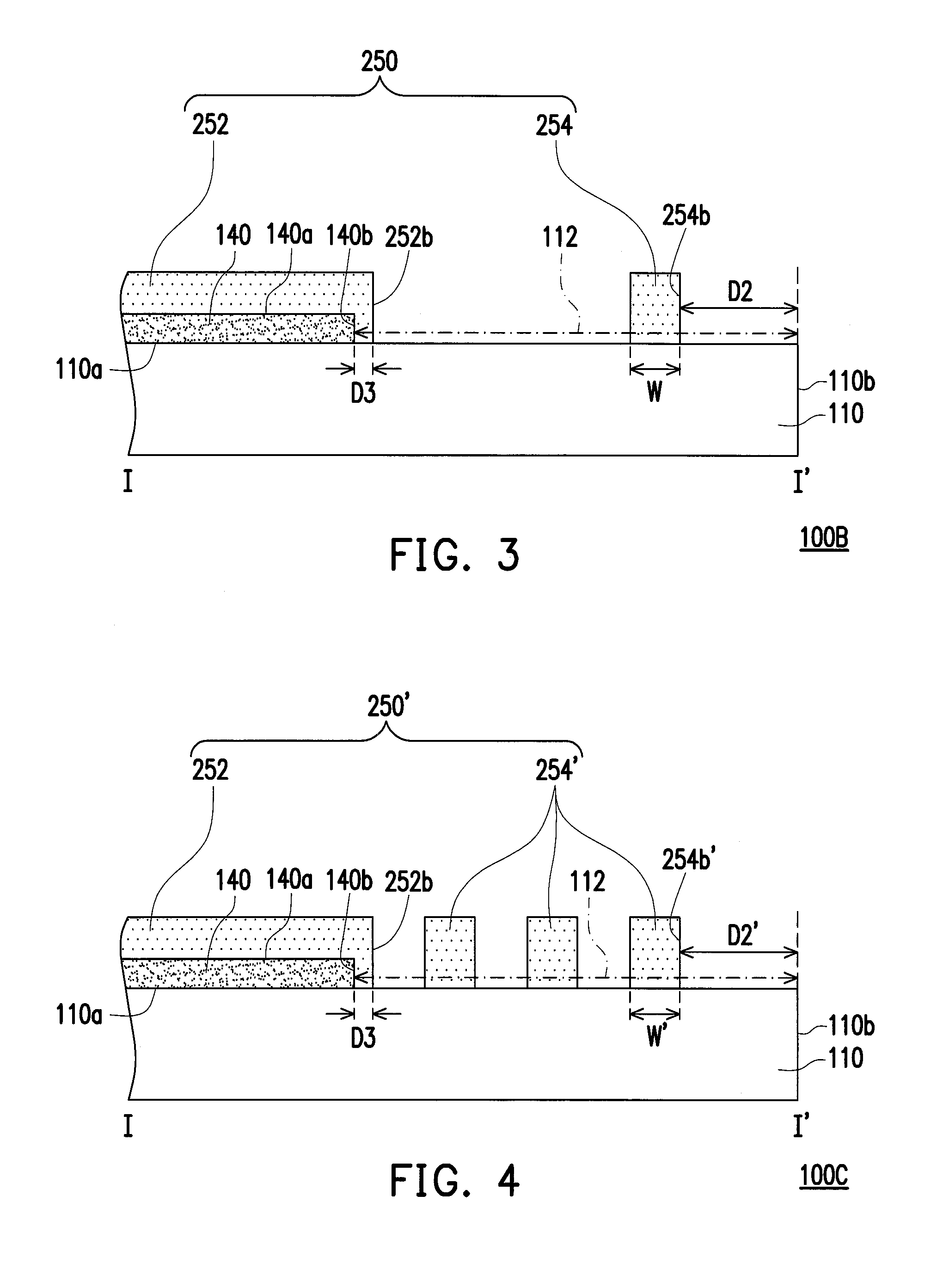
[0052]FIG. 3 is a cross-sectional view of an outer border region 112 of a decorative substrate 100B according to the invention. The embodiment of FIG. 3 is similar to the embodiment of FIG. 2, thus identical or similar elements are indicated by identical or similar reference numbers, and the descriptions thereof are not repeated. A major difference between the embodiment of FIG. 3 and the embodiment of FIG. 2 lies in that, a protective layer 250 of the decorative substrate 100B can include a first portion 252 and a second portion 254 which are separated from each other, and detailed description are described as follows.

[0053]The first portion 252 covers the decorative layer 140, and the first portion 252 further extends from the decorative layer 140 to the outer border region 112. The first portion 252 has a fourth sidewall 252b. Further, a distance D3 is provided between the fourth sidewall 252b of the first portion 252 and the second sidewall 140b of the decorative layer140.

[0054]...

third embodiment

[0056]FIG. 4 is a cross-sectional view of an outer border region 112 of a decorative substrate 100C according to the invention. The embodiment of FIG. 4 is similar to the embodiment of FIG. 3, thus identical or similar elements are indicated by identical or similar reference numbers, and the descriptions thereof are not repeated. A major difference between the embodiment of FIG. 4 and the embodiment of FIG. 3 lies in that, a protective layer 250′ of the decorative substrate 100C can include a first portion 252 and a plurality of second portions 254′, and detailed description are described as follows.

[0057]The plurality of second portions 254′ are disposed in the outer border region 112 of the first surface 110a, and the second portions 254′ are separated from the first portion 252. More specifically, the plurality of second portions 254′ are disposed between the first sidewall 110b of the substrate 110 and the fourth sidewall 252b of the first portion 252. One of the second portions...


PUM

PropertyMeasurementUnit
distanceaaaaaaaaaa
widthaaaaaaaaaa
distance D1aaaaaaaaaa

Abstract

A decorative substrate and a touch panel are provided. The decorative substrate has a first region and a second region at least partially surrounding the first region. The decorative substrate includes a substrate, a decorative layer and a protective layer. The substrate has a first surface and a first sidewall. The decorative layer is disposed on the first surface and located in the second region. The decorative layer has a second sidewall adjacent to the first sidewall of the substrate, and a portion of the first surface disposed between the second sidewall and the first sidewall is defined as an outer border region. The protective layer is at least partially disposed in the outer border region of the first surface.

Description

CROSS-REFERENCE TO RELATED APPLICATION[0001]This application claims the priority benefit of Taiwan application serial no. 102131062, filed on Aug. 29, 2013. The entirety of the above-mentioned patent application is hereby incorporated by reference herein and made a part of this specification.BACKGROUND OF THE INVENTION[0002]1. Field of the Invention[0003]The invention relates to a substrate and a panel, and more particularly to a decorative substrate and a touch panel.[0004]2. Description of Related Art[0005]As information technology, wireless mobile communication, and information electric appliances rapidly develop in recent years, input devices for many intelligent information electronic products have been changed from conventional keyboards and mice to touch panels for the purposes of convenience, miniaturization, and being user-friendly. Especially, a touch display panel has become the most popular product among all. Current touch panels mainly include capacitive, resistive, pho...

Claims


Application Information

Patent Timeline
Patent Type & Authority Applications(United States)
IPC IPC(8): G06F1/16H03K17/96
CPCG06F1/1692H03K2217/960765H03K2017/9613H03K17/9622G06F3/0412G06F2203/04103G06F1/1637G06F1/1643G06F3/0446Y10T428/24802
Inventor LIN, CHENG-YINGLIN, HAN-LUNHUANG, CHUN-MINGCHANG, CHUN-CHIN
Owner WINTEK CORP
Why Eureka
Try Eureka