Endoscope and endoscope system

an endoscope and endoscope technology, applied in the field of endoscopes and endoscope systems, can solve the problems of difficult to completely fill, reduce sealing performance, and interfere with the incident light (object image) traveling toward the image sensing device by bonding agen

Inactive Publication Date: 2015-03-05
PANASONIC INTELLECTUAL PROPERTY MANAGEMENT CO LTD
View PDF5 Cites 33 Cited by
  • Summary
  • Abstract
  • Description
  • Claims
  • Application Information

AI Technical Summary

Benefits of technology

[0012]According to this arrangement, when the closure member is fixed to the front opening of the holder member, the at least one recess serves as an air vent, and this prevents the bonding agent from being pushed out by the air exiting to the outside from inside the holder member through the space between the outer circumferential surface of the closure member and the inner circumferential surface (bonding area) of the open front end portion of the holder member.
[0013]Preferably, the outer circumferential surface of the closure member and the opposing inner circumferential surface of the open front end portion of the holder member are given a shape to engage each other so as to prevent rotation of the closure member relative to the holder member.
[0014]According to this arrangement, rotation of the closure member relative to the holder member (closure member fitting portion), which could cause chipping or peeling of the bonding agent interposed between the outer circumferential surface of the closure member and the opposing inner circumferential surface of the open front end portion of the holder member, can be prevented easily.

Problems solved by technology

In the conventional technology described in JP3737848B2, if a portion (excess portion) of the bonding agent applied to firmly fix the cover lens enters an optical path forming part (for example, an optical path between the cover lens and another lens disposed behind the cover lens) in the endoscope, a problem may arise that the bonding agent can interfere with the incident light (object image) traveling toward the image sensing device.
To prevent the undesired entrance of the bonding agent, it may be conceived to reduce the amount of bonding agent applied or to use a bonding agent having a relatively high viscosity, but in these cases, it would become difficult to completely fill the gap between the cover lens and the distal end of the main body with the bonding agent, and this can result in a reduced sealing performance.

Method used


Image

  • Endoscope and endoscope system
  • Endoscope and endoscope system
  • Endoscope and endoscope system

Examples


Embodiment Construction

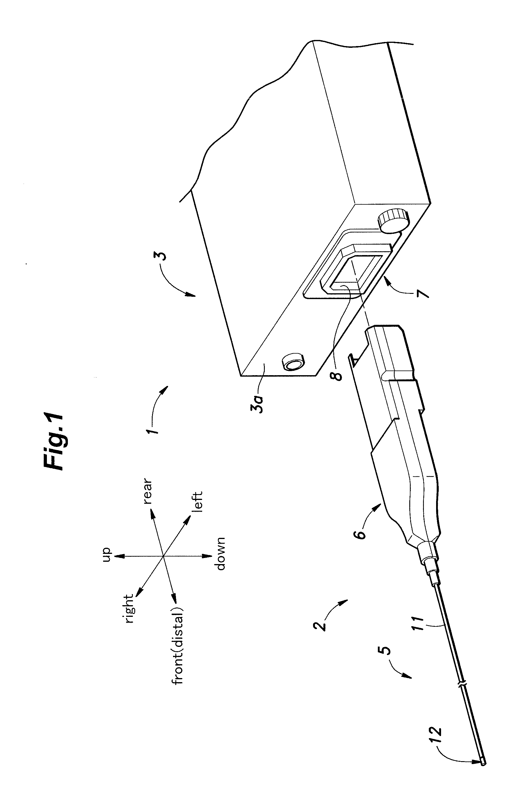
[0029]In the following, an embodiment of the present invention will be described in detail with reference to the drawings. It is to be noted that the directions referred to in the following description are basically in accordance with those shown in FIG. 1. Namely, “up” and “down” respectively correspond to an upper side and a lower side of a video processor 3, and “front (distal)” and “rear” respectively correspond to an insertion portion 5 side and a plug portion 6 side of an endoscope 2.

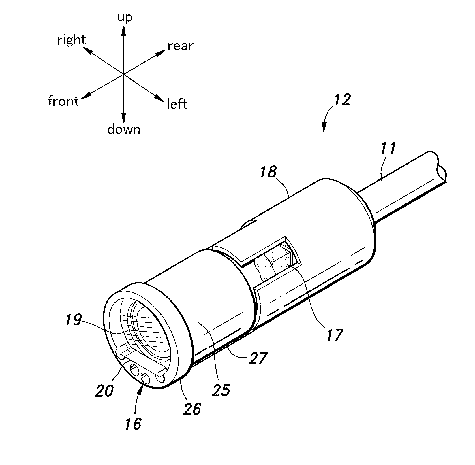
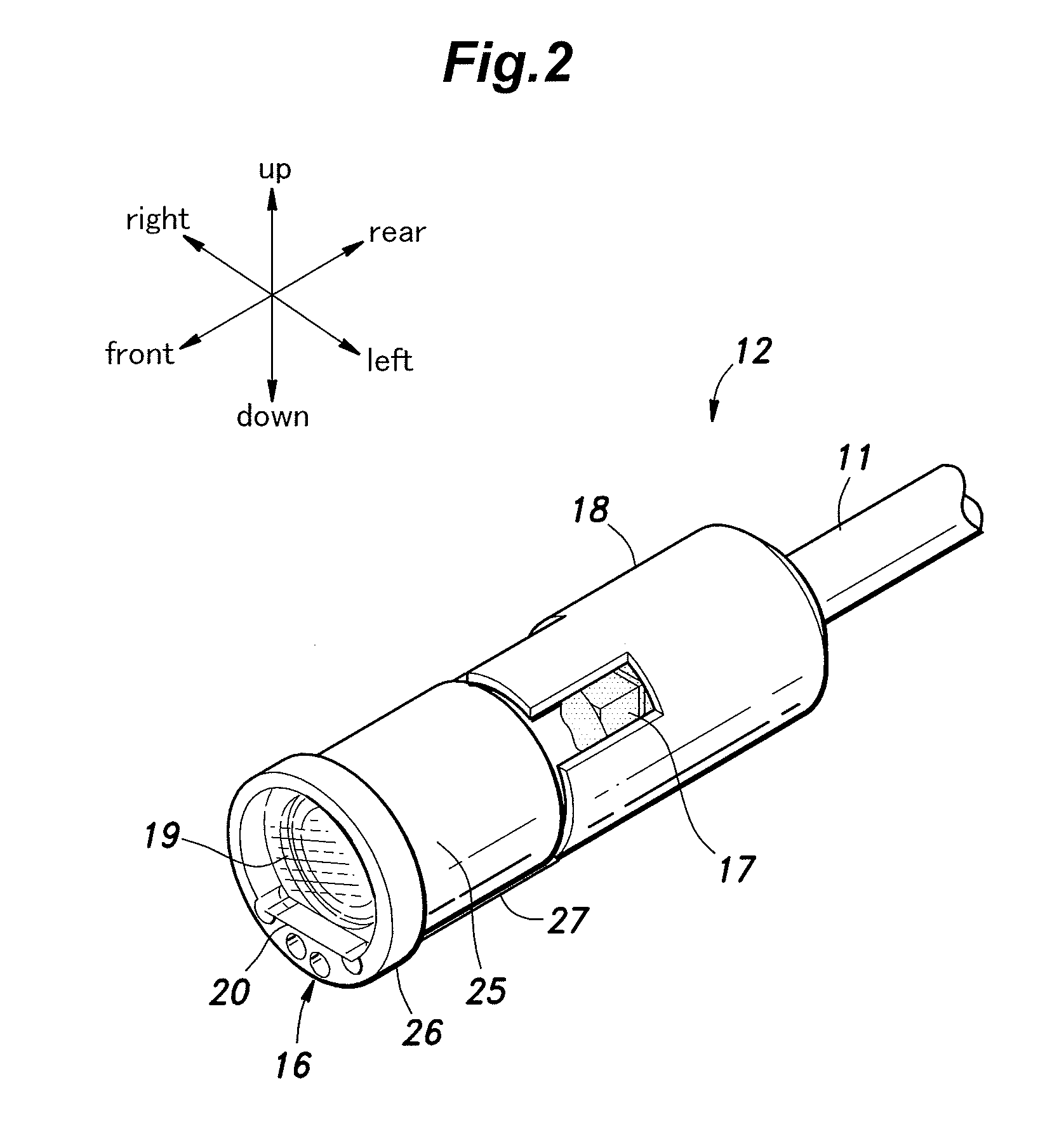
[0030]FIG. 1 is a diagram showing an overall structure of an endoscope system 1 utilizing an endoscope 2 according to an embodiment of the present invention, and FIG. 2 is a perspective view of an insertion portion distal end 12 of the endoscope 2.

[0031]As shown in FIG. 1, the endoscope system 1 mainly consists of an endoscope 2, which is a flexible scope for medical use, and a video processor (image processing device) 3 for performing known image processing, etc. on the still images and moving im...


PUM


Abstract

An endoscope having an insertion portion to be inserted into an object to be observed, includes: a substantially tubular holder member mounted to the insertion portion and having an open front end portion including a shoulder surface surrounded by an axial wall; a lens barrel holding an objective lens system and received in the holder member; and a light-transmissive closure member fitted into a front opening defined by the axial wall, and fixed to the front opening by a bonding agent interposed between an outer circumferential surface of the closure member and an opposing inner circumferential surface of the open front end portion of the holder member, wherein a space axially adjoining the shoulder surface is defined between an outer circumferential surface of a front end portion of the lens barrel and an opposing inner circumferential surface of the holder member.

Description

TECHNICAL FIELD[0001]The present invention relates to an endoscope and an endoscope system for capturing an image of an inside of an object that cannot be observed directly from outside.BACKGROUND OF THE INVENTION[0002]Endoscopes are widely used in the medical field and industrial field for capturing an image of an inside of a patient's body or capturing an image of an inside of a device or a structure. With regard to such endoscopes, it has been known to make a configuration such that, in an insertion portion of the endoscope that is to be inserted into an inside of an object to be observed, an objective lens system causes the light from a region to be imaged to be focused on a light receiving surface of an image sensor so that the light is converted to an electrical signal, which in turn is transmitted via a signal cable to an external image processing device or the like as a video signal. Such an insertion portion is required to have a sufficient sealing property for ensuring phy...

Claims


Application Information

Patent Timeline
Patent Type & Authority Applications(United States)
IPC IPC(8): A61B1/00G02B23/24G02B27/00A61B1/05G02B7/02
CPCA61B1/00096A61B1/053A61B1/00165G02B23/243G02B7/025G02B27/0006A61B1/00009A61B1/0011
Inventor HARAGUCHI, NAOYUKIKAWAUCHI, YOUSUKETANAKA, TOORUNAGAYASU, HIROSHISHIMONOSONO, KENTAKANO, YASUYUKI
Owner PANASONIC INTELLECTUAL PROPERTY MANAGEMENT CO LTD
Why Eureka
Try Eureka