Projection display with multi-channel optics with non-circular overall aperture

a projection display and overall aperture technology, applied in projectors, color televisions, television systems, etc., can solve the problems of reducing the effective area available for light transmission, large distance variations within the projected image, and reducing the luminosity, so as to improve the subjective focus behavior of the projection system

Active Publication Date: 2015-03-05
FRAUNHOFER GESELLSCHAFT ZUR FOERDERUNG DER ANGEWANDTEN FORSCHUNG EV
View PDF2 Cites 19 Cited by
  • Summary
  • Abstract
  • Description
  • Claims
  • Application Information

AI Technical Summary

Benefits of technology

[0009]According to another embodiment, a method for displaying an overall image may have the steps of: generating individual images in a distribution of sub-areas of an imaging plane; mapping, by one channel of a multi-channel optics each, one allocated sub-area of the imaging plane each, such that the mappings of the individual images are combined to an overall image in an projection area, wherein the multi-channel optics includes channels that are arranged in an elongated array oriented at least approximately like at least one elongated image feature of the overall image, so that a two-dimensional anisotropic out-of-focus behavior of each projected image point is obtained.
[0015]Embodiments are based on the fact that it is possible to unite the requirements for high image brightness and sufficient depth of focus with a certain (previous) knowledge about the image or pattern to be projected (and the appropriate structure of the image itself). Thus, the previous knowledge about the image to be projected can be used to identify directions and / or areas within the image where the image changes only slightly or not at all. Along this / these direction(s), only a relatively low depth of focus has to be obtained, at least when it is acceptable that out-of-focus effects can occur in particular at the edge of the projected overall image. In a fringe pattern used for 3D measurement, for example, the fringes define such a direction, i.e. a relatively low depth of focus is typically sufficient in parallel to the fringes, since the image content does not change anyway, or only very slightly, along this direction. In contrast, this direction can be used within the overall image to provide a larger light transmission area resulting in higher projection brightness. In other words, an overall aperture of the multi-channel optics can be anisotropic within a plane that is orthogonal to a projection direction, and thus the multi-channel optics can have a greater overall aperture in a direction along the at least one image feature than orthogonal to the same. Anisotropy of the overall aperture or the out-of-focus behavior of the multi-channel optics can show itself in particular in the change of the mapping and / or the shape of a “blur” according to the sub-aperture array: with increasing deviation of the projection distance from the ideal projection distance, the blur increasingly assumes the shape of the sub-aperture array. The anisotropy of the out-of-focus behavior can be considered as a direction dependency for directions running within one plane that is orthogonal to the projection direction and / or the optical axis of the multi-channel optics. According to embodiments, this anisotropy of the overall aperture of the multi-channel optics is oriented according to a possible anisotropy of the image content, so that an overall aperture which is lower in one direction has no (visible and / or spurious) effect on a focused display of the image to be projected. This applies even when the projection distance varies greatly within the image to be projected, for example due to a projection area which is oblique or curved with respect to the projection direction. Since the individual channels of the multi-channel optics each have a relatively small individual aperture (according to a high screen-side f-number), every individual image itself is also mapped with a respectively high depth of focus, so that image contents changing obliquely or orthogonally to the above-mentioned anisotropy direction (for example the direction parallel to the fringes of a fringe pattern) of the image are projected with a large depth of focus range within every individual image. A large depth of focus range can be combined with relatively high projection brightness without having to suffer losses in the focused display of significant or important image features.
[0033]The predominant edge direction results from the image content to be displayed. In particular, the predominant edge direction can be previously known (e.g. in the case of a fringe pattern as is used for the purposes of 3D measurement), can be determined by arithmetic averaging across the overall image content or an image section, by geometric averaging, by evaluating a gradient histogram or by other statistical evaluations. The image content transmits information evaluated and used for obtaining a technical effect, namely in particular improving the (subjective) focus behavior of the projection system, while simultaneously maintaining the desired illumination intensity or the like (or at least without having to accept serious losses in illumination intensity or the like). In other words, the suggested projection system is able to transform the blur perceived by a viewer of the projected overall image such that it is perceived less strongly in the context of the displayed image content. This effect can be compared to the effect of perceptual audio coding where portions of an audio signal that are not perceived by humans anyway are considered less or not at all during encoding and hence disappear within the noise floor. The term “edge direction” or “predominant edge direction” is not limited to edges (e.g. light-dark edges or color edges) but can also relate to moving or gradual color transitions. However, blur is typically perceived most strongly at sudden edges and corners, so that weighting in favor of hard edges can be provided.

Problems solved by technology

In a curved, discontinuous or stepped projection area, also, large distance variations can result within the projected image.
However, a higher f-number also reduces the effective area available for light transmission.
Thus, an increased f-number is typically accompanied by lower luminosity, which typically causes other problems, in particular when providing a sufficiently strong light source for the projection display.
However, part of the sub-areas of the imager or the channels of the multi-channel optics remains unused and can thus not contribute to image brightness; however the image brightness is higher than when using only one sub-area / channel and simultaneously the depth of focus is higher than when using all sub-areas / channels, at least in the direction where a depth of focus that is as high as possible is necessitated.
However, blur is typically perceived most strongly at sudden edges and corners, so that weighting in favor of hard edges can be provided.

Method used


Image

  • Projection display with multi-channel optics with non-circular overall aperture
  • Projection display with multi-channel optics with non-circular overall aperture
  • Projection display with multi-channel optics with non-circular overall aperture

Examples


Embodiment Construction

[0054]Before the present invention will be discussed in more detail below based on the figures, it should be noted that in the following embodiments the same elements or functionally equal elements are provided with the same reference numbers in the figures. Thus, a description of elements having the same reference numbers is inter-exchangeable and / or can be used in different embodiments.

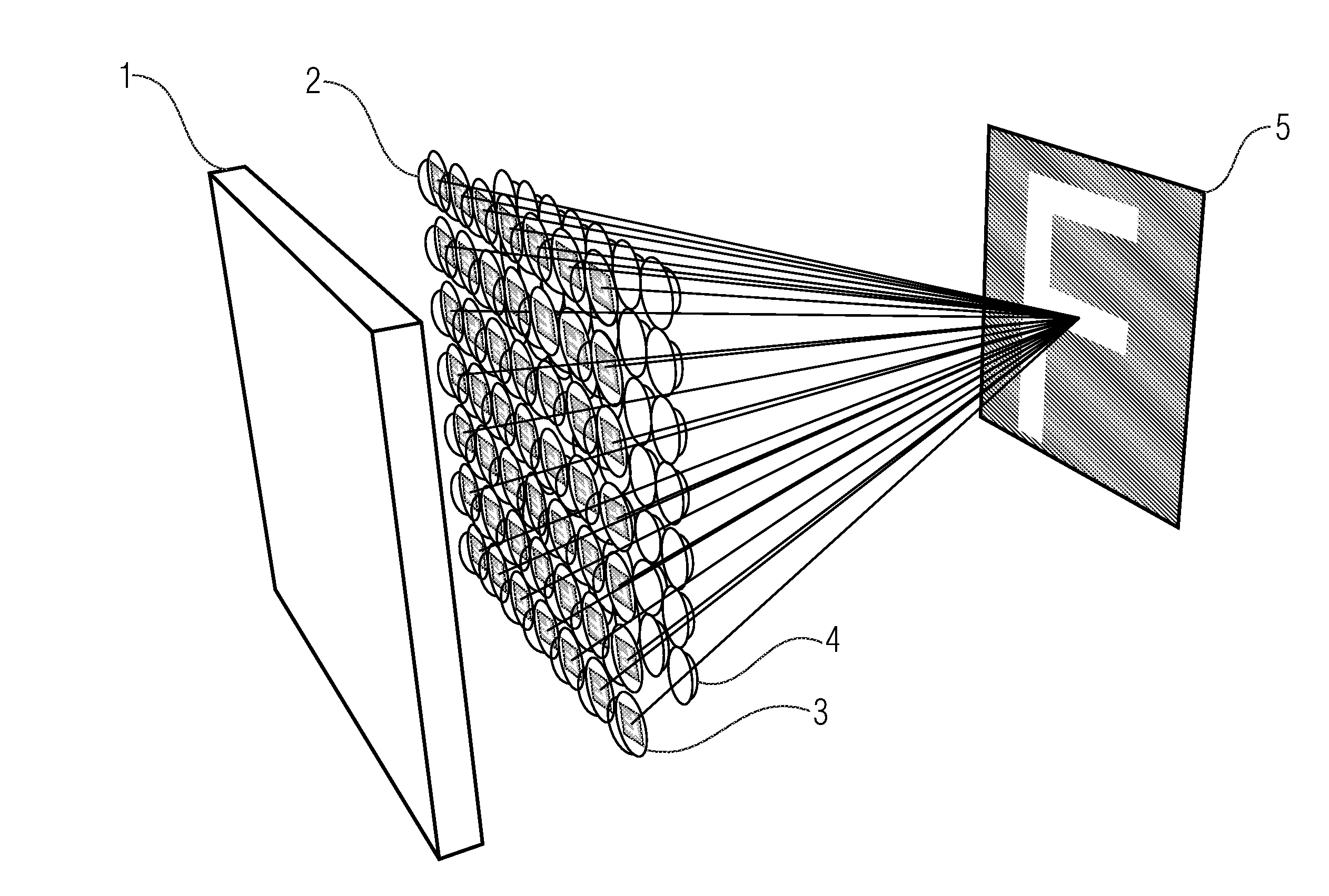
[0055]The embodiments described below relate to the manipulation (e.g. increasing the depth of focus) with high requirements with respect to system compactness and projected light flux.

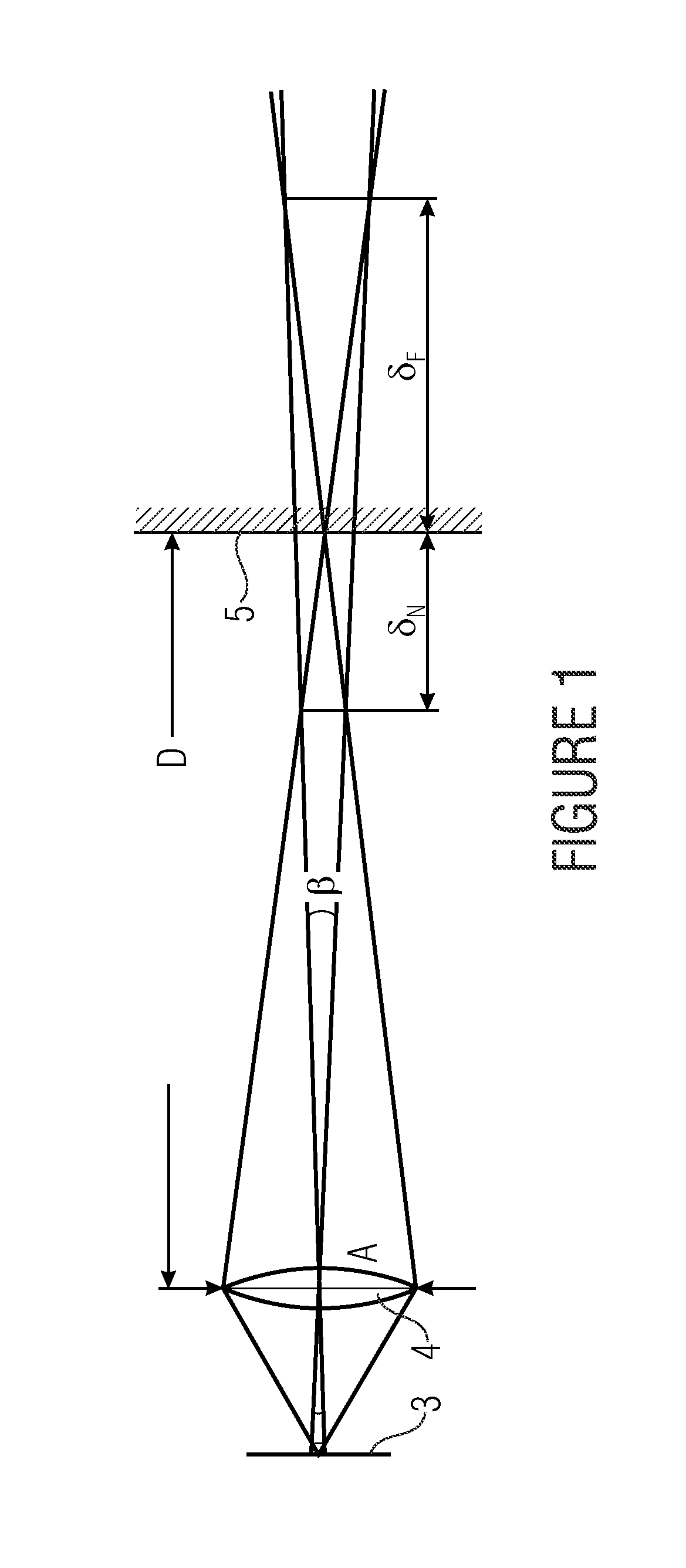
[0056]The screen-side depth of focus of a projector results according to geometrical considerations from the projection distance D, the pupil extension A and the acceptable out-of-focus angle β according to FIG. 1 by the following relation

δN,F=D2β(A±Dβ)(1)

[0057](from “Modern Optical Engineering” by W. J. Smith, McGraw-Hill, 2007). FIG. 1 shows a 2D layout for deriving the depth of focus of a classical single-aperture ...


PUM


Abstract

A projection display is provided with an imager that is implemented to generate individual images in a distribution of sub-areas of an imaging plane of the imager. The projection display also includes a multi-channel optics, which is configured to map one allocated sub-area of the imager each per channel, such that the mappings of the individual images are combined to an overall image in a projection area. At least some channels of the multi-channel optics are arranged along at least one curve which is similar to at least one elongated image feature of the overall image, so that a two-dimension anisotropic out-of-focus behavior of each projected image point is obtained. In this way, a large depth of focus range can be combined with relatively high projection brightness without having to accept losses with respect to the focused illustration of image features that are to be projected with sufficient focus.

Description

CROSS-REFERENCE TO RELATED APPLICATIONS[0001]This application is a continuation of copending International Application No. PCT / EP2013 / 059674, filed May 8, 2013, which is incorporated herein by reference in its entirety, and additionally claims priority from German Application No. 102012207621.2, filed May 8, 2012, which is also incorporated herein by reference in its entirety.BACKGROUND OF THE INVENTION[0002]Embodiments of the present invention relate to a projection display. Further embodiments of the present invention relate to a method for displaying an overall image. Further embodiments relate to a computer program for performing the method for displaying an overall image. Further embodiments of the present invention relate to an array for manipulating the mapping characteristics of a projection apparatus for different projection distances. Further embodiments of the present invention relate to a projection display having a non-circular and / or elongated overall aperture.[0003]A ...

Claims


Application Information

Patent Timeline
Patent Type & Authority Applications(United States)
IPC IPC(8): H04N9/31
CPCH04N9/3179H04N9/317H04N9/3173H04N9/3185G02B3/0056G03B21/14G01B11/2513G02B3/0037
Inventor SCHREIBER, PETERSIELER, MARCEL
Owner FRAUNHOFER GESELLSCHAFT ZUR FOERDERUNG DER ANGEWANDTEN FORSCHUNG EV
Why Eureka
Try Eureka