
Continuous wave ultraviolet laser based on stimulated raman scattering

a laser and laser technology, applied in the field of continuous wave ultraviolet laser based on stimulated raman scattering, can solve the problems of difficult to maintain interferometric accuracy for long periods of time, difficult to lock process, and high cos

Inactive Publication Date: 2015-03-05
NEWPORT CORP
View PDF1 Cites 4 Cited by
  • Summary
  • Abstract
  • Description
  • Claims
  • Application Information

AI Technical Summary

Benefits of technology

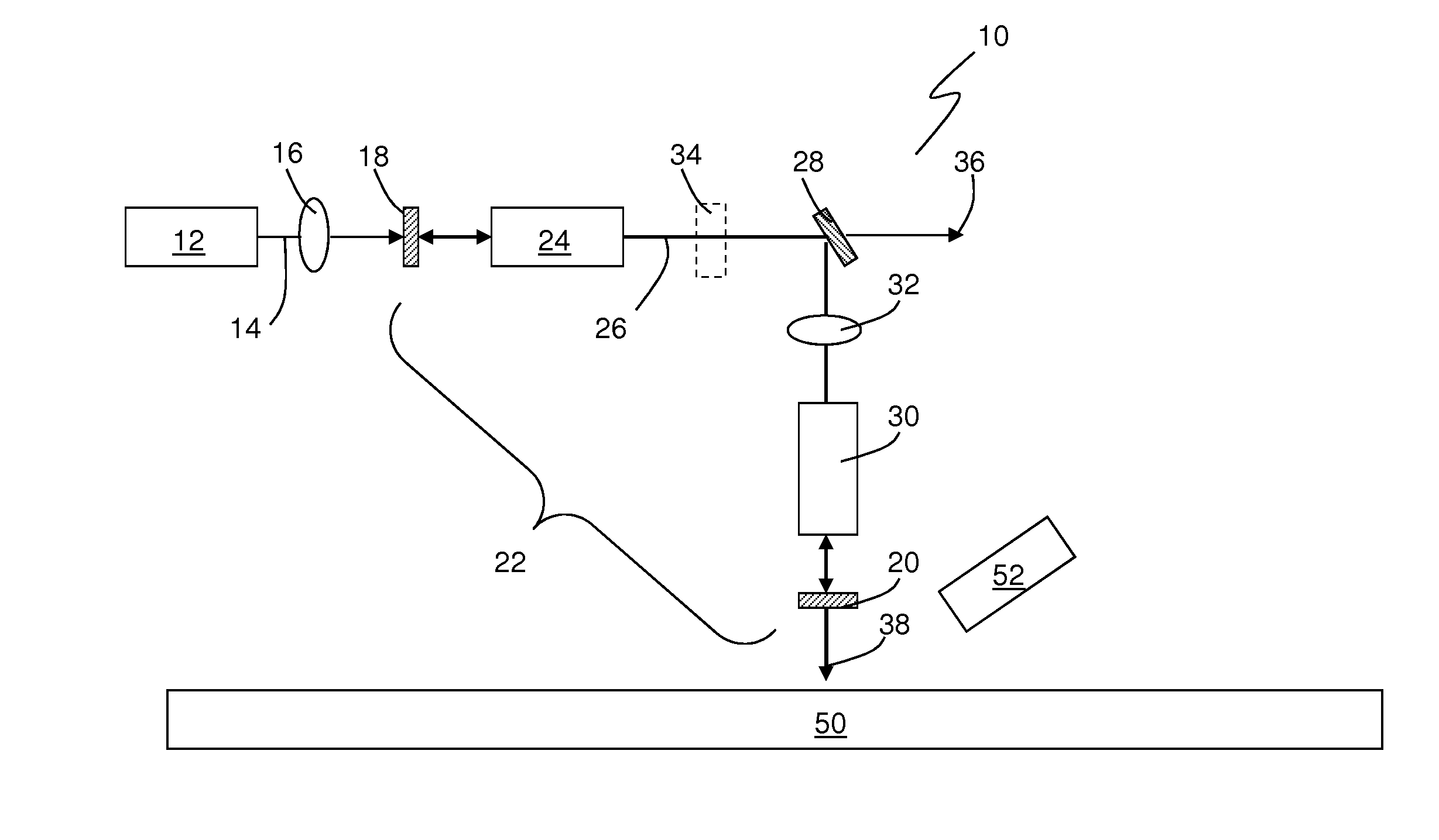
The present patent is about a laser system that generates a continuous wave output signal using a pump source, a resonant cavity, and a SRS gain device. The laser system also includes a harmonic conversion device that produces a second harmonic output signal. This laser system has advantages in inspecting semiconductor wafers and other work surfaces.

Problems solved by technology

In the past, this locking process has proven challenging and expensive.
In addition, maintaining this interferometric accuracy for long periods of time has proven difficult.

Method used


Image

  • Continuous wave ultraviolet laser based on stimulated raman scattering
  • Continuous wave ultraviolet laser based on stimulated raman scattering

Examples


Embodiment Construction

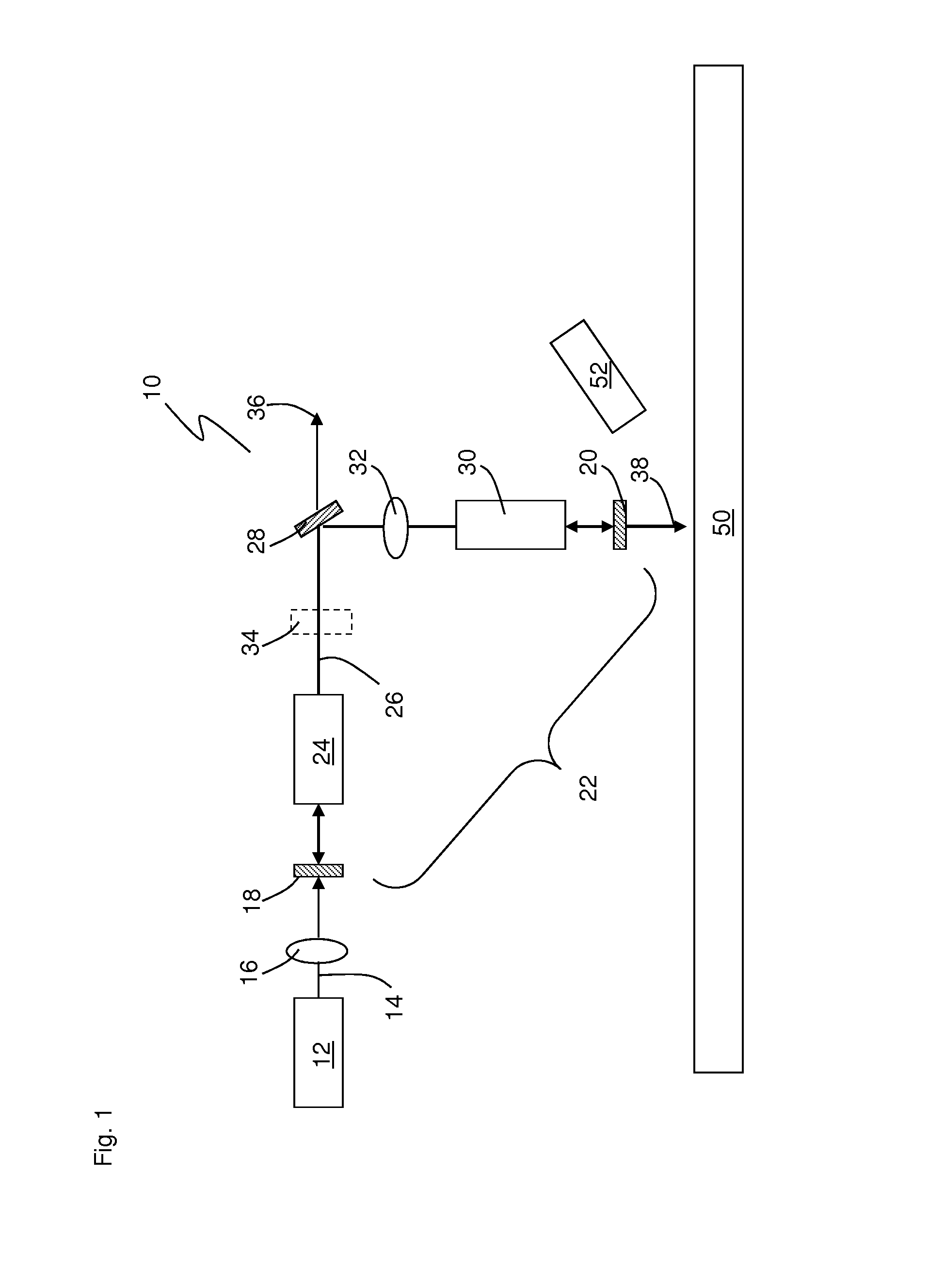
[0012]FIG. 1 shows an embodiment of a CW UV laser system 10 based on Stimulated Raman Scattering. In this process, a pump signal 14 incident on a Raman-active material 24 (hereinafter SRS gain device) generates a SRS output signal 26 (the Stokes wave) at a wavelength longer than that of the pump signal 14. The wavelength of the Stokes wave is determined by properties of the SRS gain device 24. As shown, the laser system 10 includes at least one pump laser 12 configured to output a CW pump signal 14 having a wavelength of about 400 nm to about 800 nm. In the illustrated embodiment a single pump laser 12 is used. In an alternate embodiment, multiple pump lasers 12 may be spatially and / or spectrally combined to result in the generation of one or more high power pump signals 14. Optionally, the pump laser beam may be passed through the SRS gain device 24 multiple times for increased pump intensity. In one embodiment the CW pump signal 14 has a wavelength of about 400 nm to about 800 nm....


PUM


Abstract

The present application is directed to a laser system using Stimulated Raman Scattering and harmonic conversion to produce a continuous wave ultraviolet wavelength output signal. More specifically, the laser system includes a pump source configured to generate at least one pump signal, a resonant cavity resonant at a Stokes wavelength in optical communication with the pump source, a SRS gain device positioned within the resonant cavity and configured to generate at least one SRS output signal at a Stokes wavelength when pumped with the pump signal, and a harmonic conversion device positioned within the resonant cavity and configured to produce a continuous wave second harmonic output signal of the SRS output signal.

Description

CROSS REFERENCE TO RELATED APPLICATIONS[0001]The present application claims priority to U.S. Provisional Patent Application Ser. No. 61 / 611 / 994, entitled “Continuous Wave Ultraviolet Laser Based on Stimulated Raman Scattering,” filed on Mar. 16, 2012, the entire contents of which are incorporated by reference herein.BACKGROUND[0002]Numerous material processing and diagnostic applications, such as semiconductor processing and inspection, requires powerful diffraction-limited continuous wave (hereinafter CW) ultraviolet (hereinafter UV) laser light. Presently, the most efficient and practical CW laser sources operate at wavelengths considerably longer than UV wavelengths, thereby requiring harmonic conversion to a desired UV wavelength. For example, CW laser light sources outputting near IR wavelengths or longer may be used as a source.[0003]One common CW laser source frequently used in industrial applications is a solid-state Nd laser system configured to output a laser signal at abo...

Claims


Application Information

Patent Timeline
IPC IPC(8): H04B10/50H04B10/572
CPCH04B10/572H04B10/503H01S3/094038H01S3/109H01S3/30
Inventor PETERSEN, ALAN B.KAFKA, JAMES D.
Owner NEWPORT CORP
Learn More