Guide blade ring for an axial turbomachine and method for designing the guide blade ring

a technology of axial turbomachines and guide blade rings, which is applied in the direction of machines/engines, liquid fuel engines, forging/pressing/hammering apparatus, etc., can solve the problems of vibration excitation of blades and the need to exchange guide blades, and achieve the effect of being susceptible to vibration excitation

Inactive Publication Date: 2015-03-05
SIEMENS AG
View PDF7 Cites 5 Cited by
  • Summary
  • Abstract
  • Description
  • Claims
  • Application Information

AI Technical Summary

Benefits of technology

[0005]Embodiments of the invention are based on an object of achieving a stage for an axial turbomachine, the axial turbomachine having the stage and a method for designing the stage, wherein the abovementioned problems are overcome and the rotor blades of the stage have a long service life.
[0009]The rotor blades may be subjected to two different vibration excitation mechanisms, namely flutter and a forced response. Flutter is a self-excited vibration in which energy from the flow is transferred into the vibrations of the rotor blades. Flutter is excited by small blade vibrations, which can be self-energizing, such that the blade vibrates more strongly with every subsequent vibration period. This can cause the rotor blades to break off. The fact that the dividing angle varies means that, in the case of two adjacent ducts, the flow deflection angle is different, whereby the flow from the guide blade ring to the rotor blade ring is irregular over the circumference of the axial turbomachine. This changes the loading on the rotor blades in the course of a rotation, which advantageously reduces flutter.
[0013]The guide blades are preferably designed such that none of the eigenfrequencies of the rotor blades corresponds with the rotational frequency of the axial turbomachine or with a multiple of the rotational frequency up to and including the eighth multiple of the rotational frequency. It is thus advantageously ensured that, when the axial turbomachine is in operation, there is no coupling between the rotation of the axial turbomachine and the vibrations of the rotor blades. The coupling can lead to an increased energy input from the flow into the vibrations.
[0015]The stage according to an embodiment of the invention is designed using the method according to another embodiment of the invention. The axial turbomachine according to an embodiment of the invention has the stage, in particular as the last, downstream stage of the axial turbomachine. The rotor blades in the last stage of the axial turbomachine are those rotor blades having the longest radial extent in the axial turbomachine and are thus particularly susceptible to vibration excitation. A non-periodic vibration excitation of the rotor blades is thus advantageous particularly in the last stage.

Problems solved by technology

When the steam turbine is in operation, the blades may be excited into vibration.
The stress loading due to the vibration is high particularly at the blade roots, such that material fatigue may arise at the blade roots, making it necessary to exchange the guide blades, which is cost-intensive.

Method used


Image

  • Guide blade ring for an axial turbomachine and method for designing the guide blade ring
  • Guide blade ring for an axial turbomachine and method for designing the guide blade ring
  • Guide blade ring for an axial turbomachine and method for designing the guide blade ring

Examples


Embodiment Construction

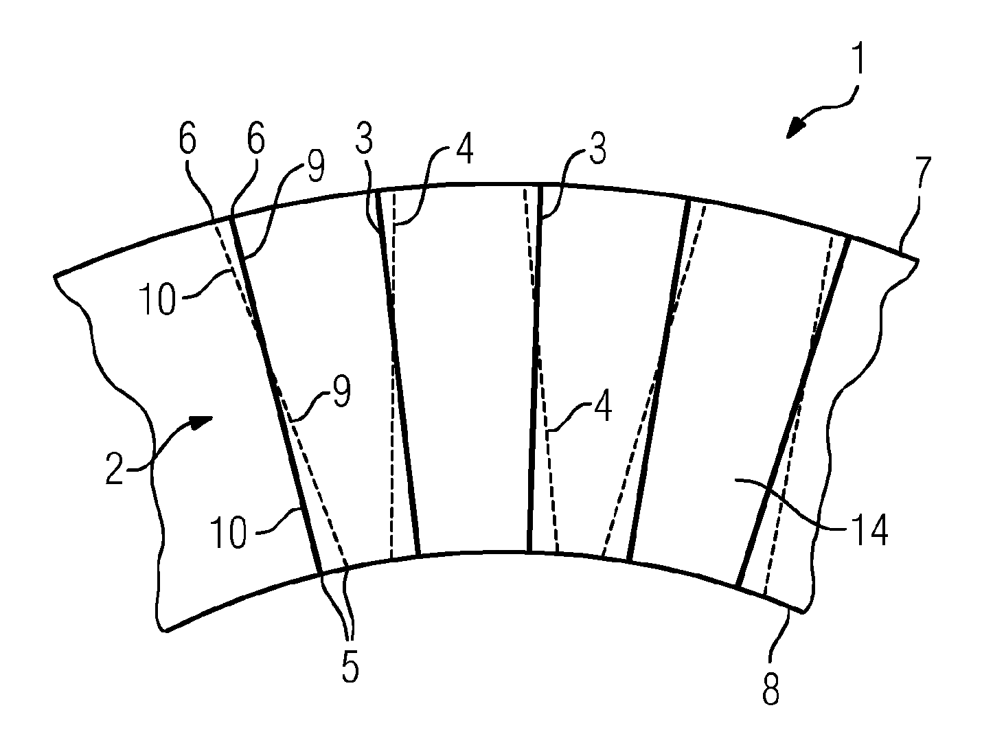
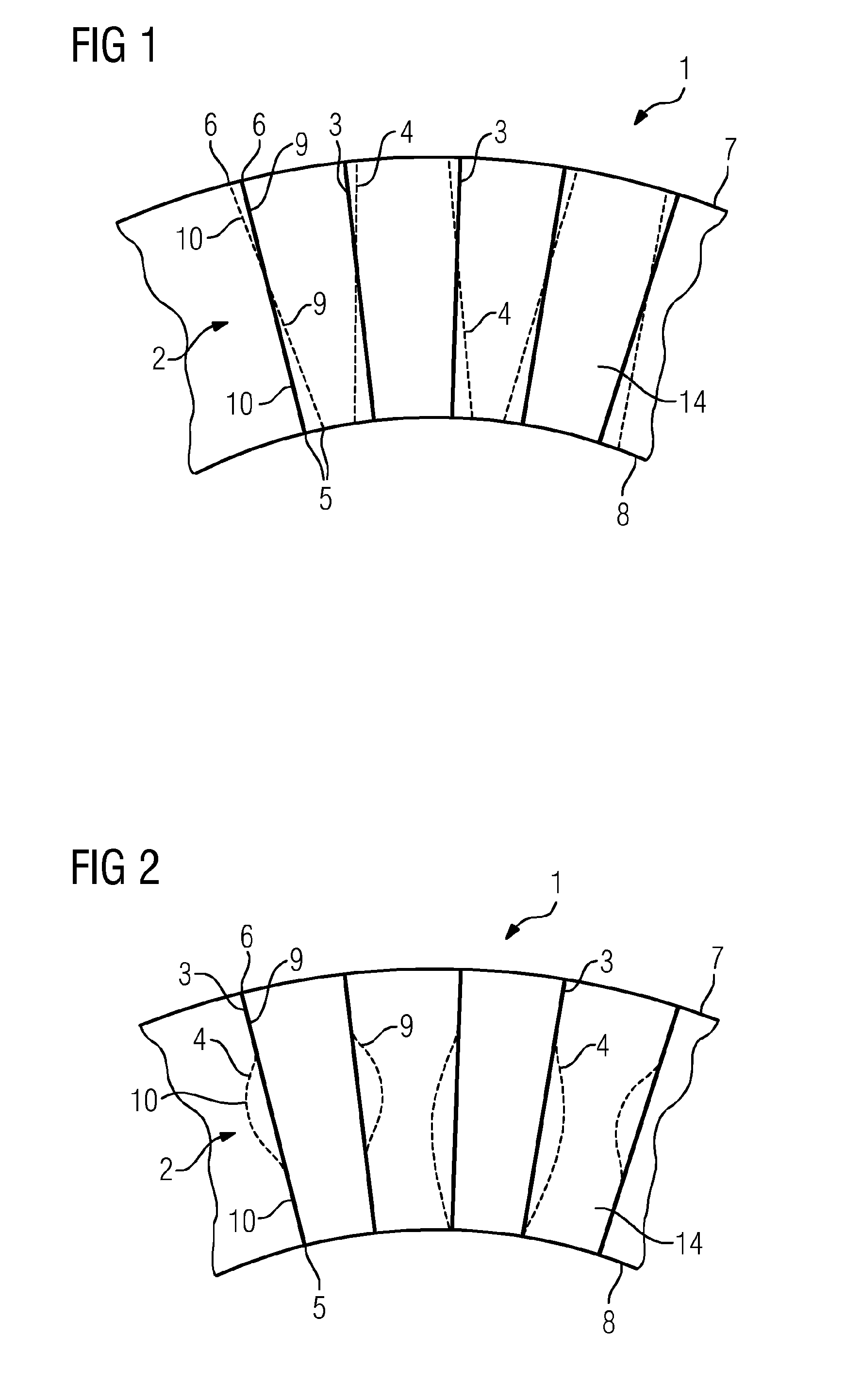
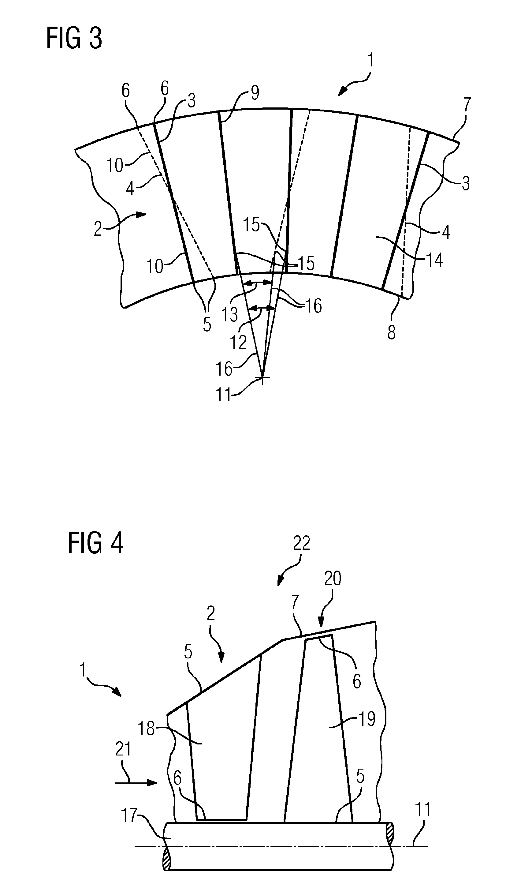
[0019]As shown in FIGS. 1 to 3, an axial turbomachine 1 has a guide blade ring 2 and a casing 7. The guide blade ring 2 has a plurality of guide blades 3, 4, with each of the guide blades 3, 4 having a blade root 5, a blade tip 6, a pressure side 9 and a suction side 10. Each of the guide blades 3, 4 is securely attached to the casing by means of its blade tip 6 and to a hub ring 8 by means of its blade root 5. A duct 14, in which a working fluid can be made to flow, is formed between two adjacent guide blades 3, 4. FIGS. 1 to 3 each show the trailing edge of the guide blades 3, 4.

[0020]FIG. 3 shows, by way of example, a dividing angle 13 of the axial turbomachine 1. A surface point 15 is represented on each of the two adjacent guide blades 3, 4, on the trailing edges of the guide blades 3, 4. In that context, the two surface points 15 are at the same distance from the axis 11 of the axial turbomachine 1. FIG. 3 also shows two connection lines 16 which proceed from each of the two s...


PUM

PropertyMeasurementUnit
circumferenceaaaaaaaaaa
mechanicalaaaaaaaaaa
heightaaaaaaaaaa

Abstract

A method for designing a stage for an axial turbomachine having a guide blade ring and a rotor blade ring arranged downstream of the guide blade ring is provided. The method includes: profiling a guide blade ring having guide blades arranged regularly over the circumference of the guide blade ring in accordance with basic aerodynamic and mechanical conditions; moving at least one profile section of at least one of the guide blades in the circumferential direction in such a way that the pitch angle for the at least one guide blade and a guide blade arranged adjacent thereto varies over the blade height in such a way that during operation of the axial turbomachine the departing flow formed downstream of the guide blade ring is irregularly formed over the circumference of the axial turbomachine, such that the vibration excitation of the rotor blades of the rotor blade ring is low.

Description

CROSS REFERENCE TO RELATED APPLICATIONS[0001]This application is the U.S. National Stage of International Application No. PCT / EP2013 / 057170 filed Apr. 5, 2013, and claims the benefit thereof. The International Application claims the benefit of European Application No. EP12164299 filed Apr. 16, 2012. All of the applications are incorporated by reference herein in their entirety.FIELD OF INVENTION[0002]The invention relates to a guide blade ring for an axial turbomachine, to the axial turbomachine and to a method for designing the guide blade ring.BACKGROUND OF INVENTION[0003]In a steam turbine, steam is expanded to generate rotational energy. The steam turbine has a plurality of stages, each stage having a guide blade ring with a plurality of guide blades and a rotor blade ring with a plurality of rotor blades. The rotor blades are fitted to the shaft of the steam turbine and rotate during operation of the steam turbine; the guide blades are fitted to the housing of the steam turbine...

Claims


Application Information

Patent Timeline
Patent Type & Authority Applications(United States)
IPC IPC(8): F01D25/04F01D5/10F01D9/04
CPCF01D25/04F01D9/041F05D2230/00F05D2260/961F01D5/10F01D5/142F01D5/16Y10T29/4932
Inventor RICHTER, CHRISTOPH HERMANNSTUER, HEINRICH
Owner SIEMENS AG
Why Eureka
Try Eureka