Coaxial ground heat exchanger and method for installing said ground heat exchanger in the ground

a ground heat exchanger and coaxial technology, applied in the direction of fluid removal, insulation, survey, etc., can solve the problems of large pressure drop of heat transfer medium, large portion of the available cross-section of the ground heat exchanger hole, and relatively modest energy efficiency of u-tube exchangers

Active Publication Date: 2015-03-12
BRODER AG
View PDF12 Cites 21 Cited by
  • Summary
  • Abstract
  • Description
  • Claims
  • Application Information

AI Technical Summary

Benefits of technology

[0040]A coaxial ground heat exchanger that is designed according to the disclosure with a central core tube, which is provided with a heat-insulating casing, and a hose-like covering that is converted from an originally folded state into a stable expanded state, which at the same time forms the jacket tube of the coaxial ground heat exchanger and in the mounted state of the coaxial ground heat exchanger adjoins a wall of a ground heat exchanger hole, is, for example, suitable for operation with water as a heat transfer medium. Water as a heat transfer medium has the advantage that it also can result in no contamination in the event of a deliberate or accidental exiting of the heat transfer medium from the coaxial ground heat exchanger. As a result, the coaxial ground heat exchanger according to the disclosure is also suitable for use in areas that have long been considered restricted areas for reasons of groundwater protection.

Problems solved by technology

As a result of this undesirable release of heat, the exergetic efficiency of U-tube exchangers is relatively modest.
While deep-reaching coaxial ground heat exchangers with insulated core tubes relative to the other known types of ground heat exchangers have a major exergetic advantage relative to the quality of the applicable heat flux, they also have the drawback of a large pressure drop of the heat transfer medium.
That is, a large portion of the available cross-section of the ground heat exchanger hole is lost owing to the cross-sectional surface area of the heat insulation of the central core tube, owing to the relatively large wall thickness of the jacket tube of the coaxial ground heat exchanger, and in particular owing to the filling layer that is injected after the installation of the exchanger, for example, a mixture that can include (e.g., consist of) bentonite and cement, between the jacket tube of the exchanger and the surrounding soil.

Method used


Image

  • Coaxial ground heat exchanger and method for installing said ground heat exchanger in the ground
  • Coaxial ground heat exchanger and method for installing said ground heat exchanger in the ground
  • Coaxial ground heat exchanger and method for installing said ground heat exchanger in the ground

Examples


Embodiment Construction

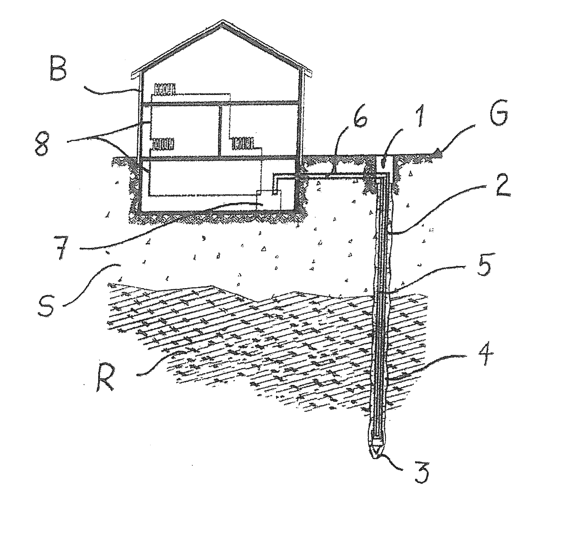
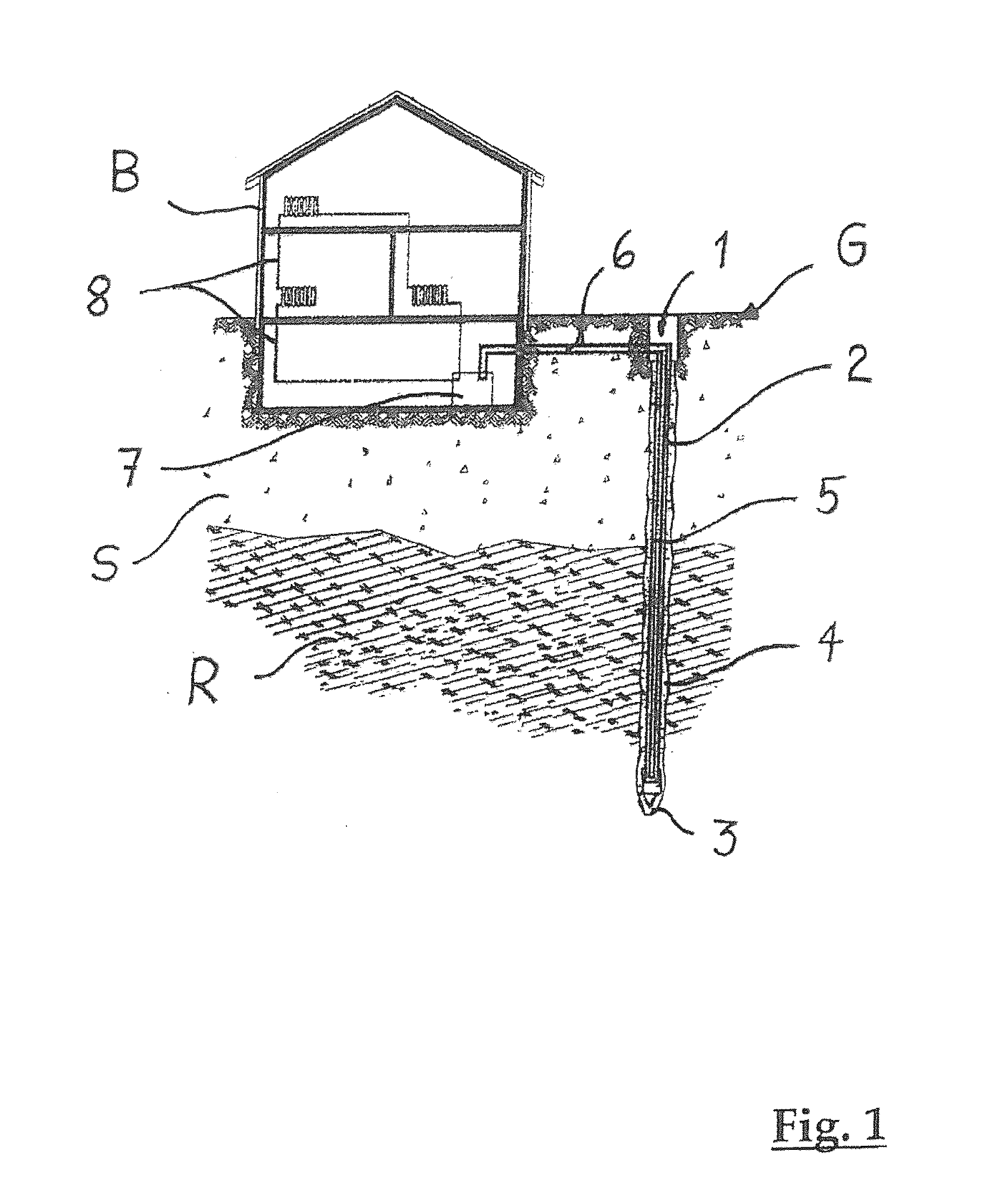
[0017]A coaxial ground heat exchanger is disclosed, which has a lower pressure drop for the circulating heat transfer medium and allows a higher uptake of heat energy of the surrounding soil in the heat transfer medium. A method for mounting a coaxial ground heat exchanger in the soil is also disclosed, which can be implemented simply and economically and can take into account the specifications of environmental and water protection.

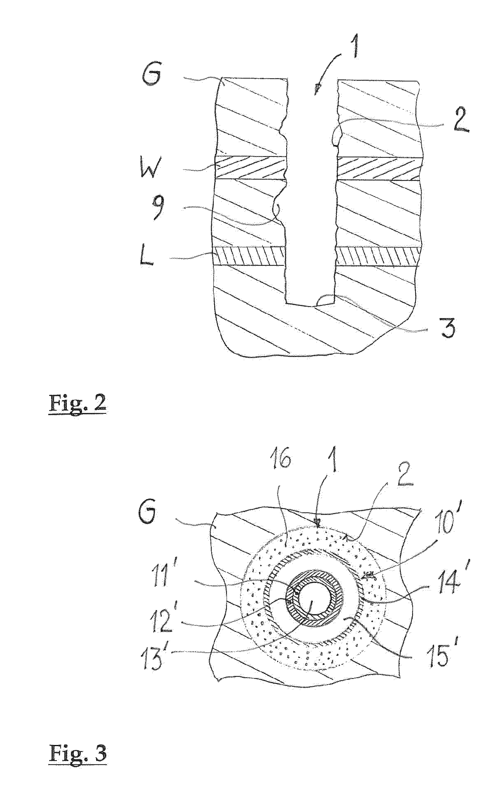
[0018]An exemplary coaxial ground heat exchanger is disclosed with a central core tube and a jacket tube, which delimits an annular gap that extends radially outward form the core tube, whereby the core tube and the annular gap are designed for a free-flowing heat transfer medium to flow between them. According to an exemplary embodiment, the jacket tube of the coaxial ground heat exchanger in the installed state of the ground heat exchanger directly adjoins a wall of a ground heat exchanger hole.

[0019]An exemplary concept disclosed herein includes modif...


PUM


Abstract

A coaxial ground heat exchanger and installation method are disclosed where the heat exchanger has a central core tube that can be provided with a thermally insulating casing and an outer tube that delimits an annular gap which extends radially outwards from the core tube. The core tube and the annular gap can be configured such that a flowable heat transfer medium can flow through. The outer tube is formed by a tubular expandable cover that directly adjoins a wall of a ground heat exchanger borehole when the heat exchanger is installed.

Description

RELATED APPLICATIONS[0001]This application claims priority as a continuation application under 35 U.S.C. §120 to PCT / CH2013 / 000055, which was filed as an International Application on Mar. 27, 2013 designating the U.S., and which claims priority to Swiss Application 681 / 12 filed in Switzerland on May 14, 2012. The entire contents of these applications are hereby incorporated by reference in their entireties.FIELD[0002]The present disclosure relates to a coaxial ground heat exchanger. In addition, the present disclosure also relates to a method for mounting underground a coaxial ground heat exchanger.BACKGROUND INFORMATION[0003]The foreseeable scarcity of fossil energy sources and the necessity to reduce the emissions of air pollutants and CO2 have led to a rethinking in the production of heat and the use of alternative, renewable energy, such as pollutant-free technologies, to ensure greater acceptance. An especially attractive form of heat production is the use of downhole heat. Dow...

Claims


Application Information

Patent Timeline
Patent Type & Authority Applications(United States)
IPC IPC(8): F24J3/08E21B36/00E21B3/00
CPCF24J3/081E21B36/00E21B3/00F24T10/17F24T2010/53F24T10/30F24T10/10Y02E10/10F24T10/00F28D7/12
Inventor BRODER, MATHIAS
Owner BRODER AG
Why Eureka
Try Eureka