Intradermal Injection Device

Active Publication Date: 2015-03-12
NOVOSANIS NV
View PDF2 Cites 25 Cited by
  • Summary
  • Abstract
  • Description
  • Claims
  • Application Information

AI Technical Summary

Benefits of technology

[0016]It is an advantage of the present invention that the plunger is frictionally mounted to the reservoir, whereby the force required to move the plunger relative to the reservoir is at least a predefined amount larger than the force required to move the reservoir with respect to the housing. This has the effect that, when a force is applied to the plunger, the plunger and the reservoir and the needle will move together towards the opening, while maintaining their relative position. This initial movement will cause the needle to penetrate the subject's skin, while minimal or substantially no pressure is exerted on the fluid in the reservoir (because the position between the plunger and the reservoir is maintained), hence no or only a limited amount of fluid will leave the needle before being inserted in the skin. The plunger and reservoir and needle will typically move towards the opening until a predefined end position is reached, corresponding to a predefined depth of the needle into the subject's skin, at which point they come to a stop. When a force higher than the force required to overcome the friction between the plunger and the reservoir is then exerted upon the plunger, the reservoir and the needle will maintain their position, but the plunger will move relative to the reservoir, and will thereby squeeze the fluid out of the reservoir, through the needle, and into the subject's skin. Thus the friction between the plunger and the reservoir makes sure that the needle is first inserted into the subject's skin, before pressure is exerted upon the fluid in the reservoir, so that spilling of the fluid is avoided, and the amount of overfill can be reduced.
[0017]It is noted that the same effect will happen also when a force larger than the force required to overcome the friction between the plunger and the reservoir is exerted on the plunger already from the start, hence the same effect is obtained irrespective of the force profile applied on the plunger.
[0018]It is noted that the predetermined value of at least 0.5 Newton is chosen on the one hand as larger than the force required to insert the

Problems solved by technology

This requires the vaccinator to judge the angle and depth of needle insertion by eye/feel, which requires special training

Method used


Image

  • Intradermal Injection Device
  • Intradermal Injection Device
  • Intradermal Injection Device

Examples


case 5

Assembly Step 5: Reservoir 3 and Case 5

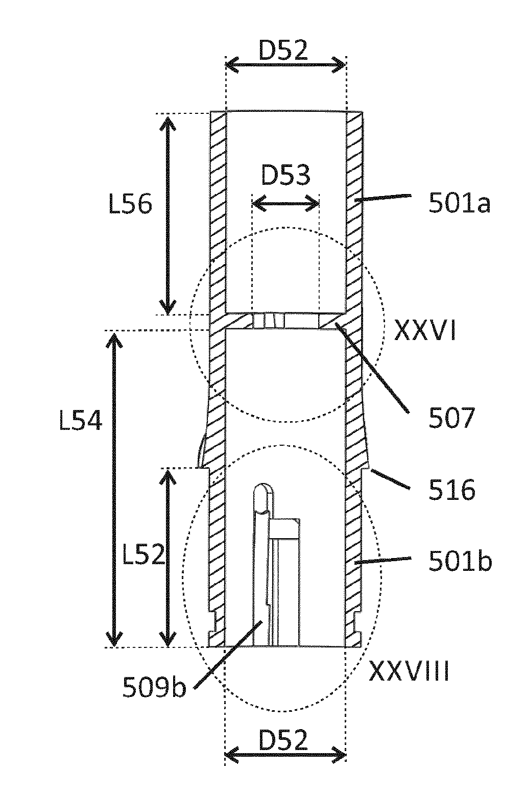
[0202]The reservoir 3 may then be mounted in case 5 by sliding the pens 308a and 308b of the reservoir 3 (FIG. 14) through the grooves 512a and 512b of the case 5 (FIG. 28), until they snap into the third grooves 511a and 511b of the case 5. The outer surface of reservoir 3 with diameter D35 (FIG. 8) may be guided by the inner surface of the case 5 with diameter D52 (FIGS. 12 and 14).

Assembly Step 6: Foot 1 and Case 5

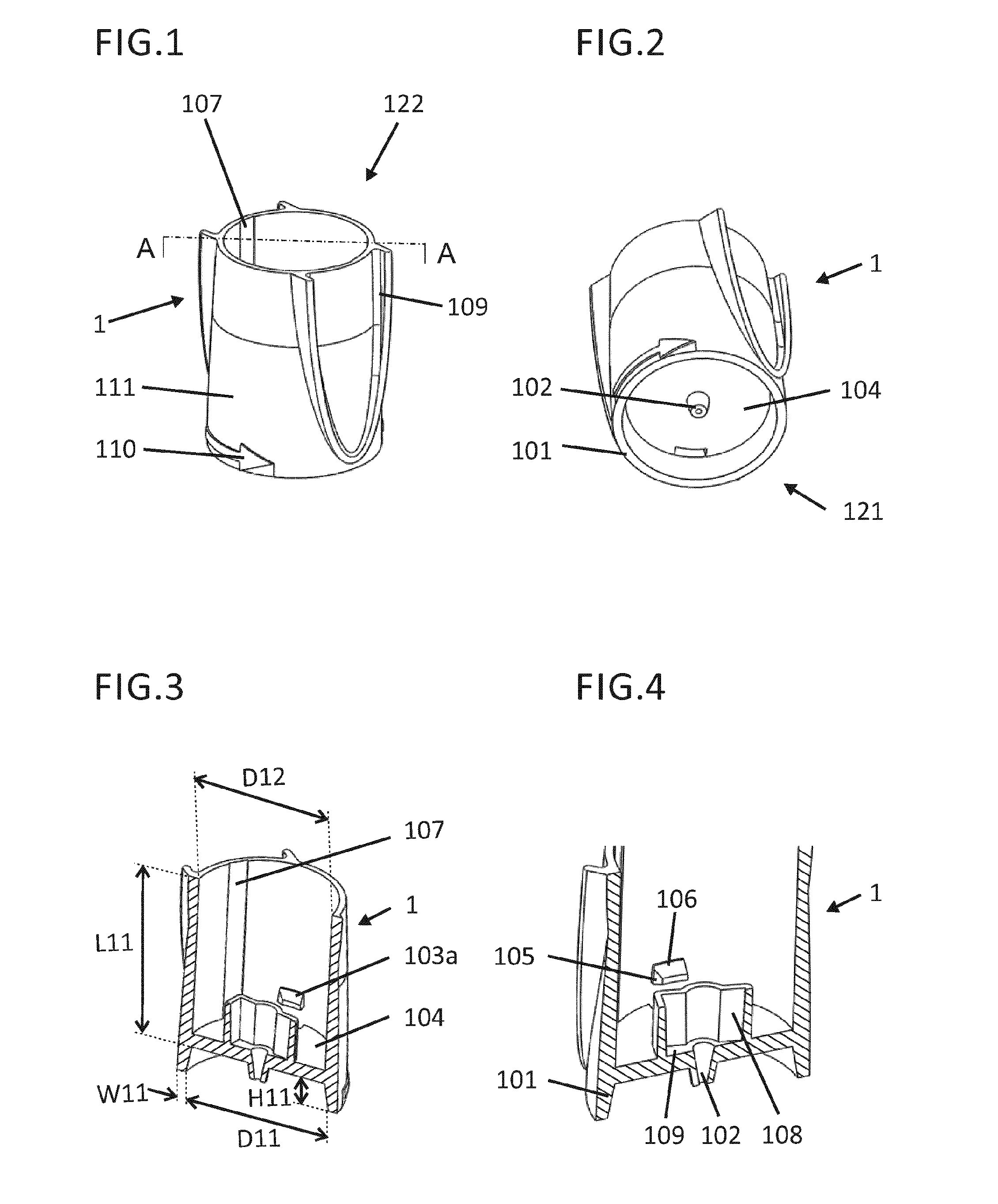
[0203]The foot 1 may be snapped in case 5 by guiding the pens 103 (FIG. 3, FIG. 4) through the insertion portions 506a and 506b (FIG. 22 and FIG. 30), and forcing the pens 103 into the circumferential grooves 502. The inner surface of the foot 1 with diameter D12 (FIG. 3) may be guided by the outer surface of the case 5 with diameter D51 (FIG. 21).

Assembly Step 7: Plunger 6 and Spring 8

[0204]The spring 8 may be forced over snap heads 605a and 605b of the plunger 6 (FIG. 32). The spring 8 may be centred with respect to the secondary...


PUM


Abstract

An intradermal injection device comprises a housing, a foot with an opening for passage of a needle; a reservoir movably mounted in the housing, and having a hollow space for holding a fluid; a hollow needle movably mounted in the housing and having a first end for penetrating the subject's skin and a second end for penetrating the reservoir, a plunger movably mounted in the housing for moving the needle through the opening for penetrating the subject's skin, and for pressing the fluid out of the reservoir. The reservoir is frictionally mounted inside the housing by first friction means, and the plunger is frictionally mounted to the reservoir by second friction means. The force to overcome the second friction is larger than the force to overcome the first friction.

Description

FIELD OF THE INVENTION[0001]The present invention relates to the field of intradermal injection devices, more specifically to the field of prefillable or prefilled injection devices. The present invention relates to the devices per se, methods of manufacturing and methods of operation thereof.BACKGROUND OF THE INVENTION[0002]The vast majority of vaccines are administered into the muscle (intramusculary, IM) or into subcutaneous fat (subcutaneously, SC) using needle and syringe. Mammalian skin is composed of two primary layers: the epidermis and the dermis. The epidermis is the outer layer of the skin and it has a thickness of 150-200 μm, while the dermis which is the inner layer has a thickness of 1.5-3.0 mm. The skin thickness varies with age, gender and anatomic site, but also racial and regional differences have been reported. Underlying the dermis is the hypodermis which is not part of the skin, but connects the skin to bone and muscle.[0003]The standard procedure for intraderma...

Claims


Application Information

Patent Timeline
IPC IPC(8): A61M5/315A61M5/32
CPCA61M5/31501A61M5/3232A61M2005/31508A61M2005/3151A61M5/2425A61M5/326A61M5/2466A61M5/3272A61M5/3293A61M5/3271A61M5/345A61M5/425A61M5/46
Inventor VAN DAMME, PIERREVANKERCKHOVEN, VANESSAVERWULGEN, STIJNCAMERLYNCK, RUBENCOEMANS, WOUTERSCHEELEN, LINDABEYERS, KOEN CATHARINA LODEWIJKVERLEIJE, BARTBOUDEWIJNS, WIM
Owner NOVOSANIS NV
Why Eureka
Try Eureka