

Retractable Flow Maintaining Stent
- Summary
- Abstract
- Description
- Claims
- Application Information
AI Technical Summary
Benefits of technology
Problems solved by technology
Method used
Image

Examples
Embodiment Construction
[0039]The following detailed description is of the best presently contemplated mode of carrying out the invention. The description is not intended in a limiting sense, and is made solely for the purpose of illustrating the general principles of the invention. The various features and advantages of the present invention may be more readily understood with reference to the following detailed description taken in conjunction with the accompanying drawings.
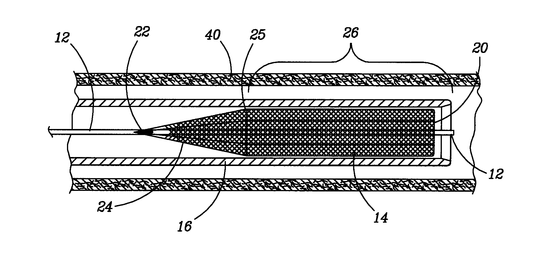
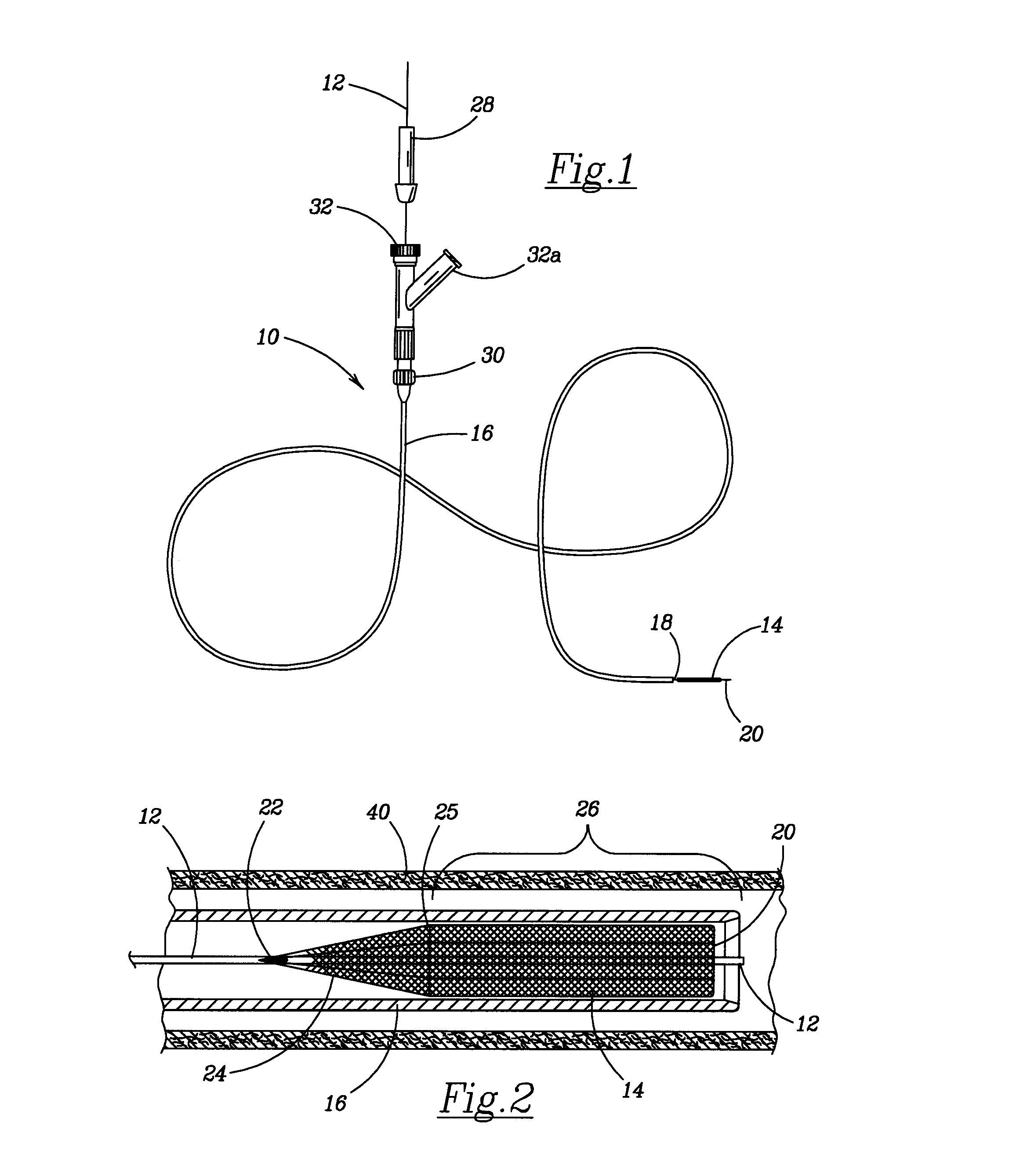
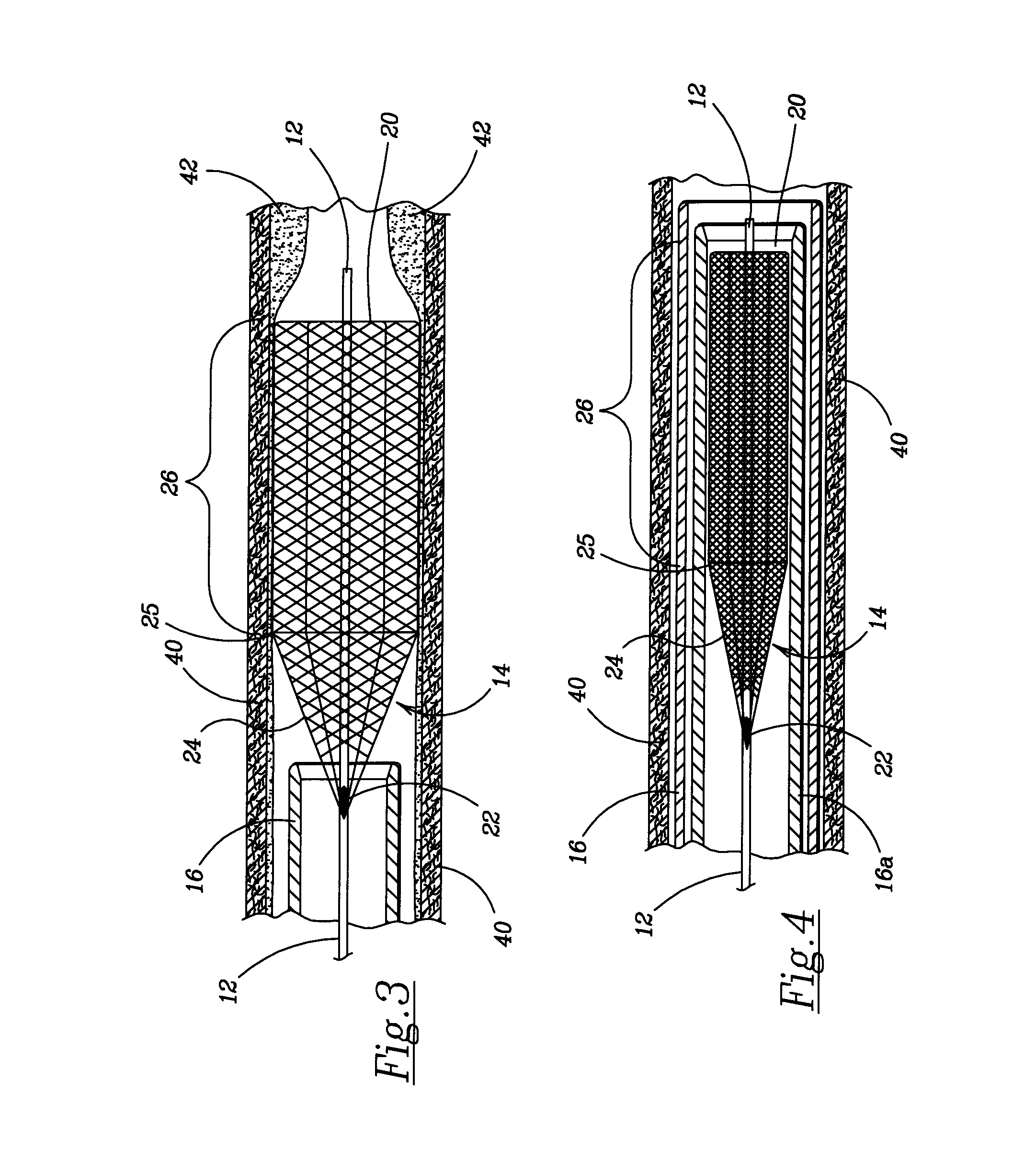
[0040]Various embodiments of the retractable flow maintaining stent wire for delivering and retracting a self-expanding stent in accordance with the invention are described herein. Referring now to the drawings in detail, where like numerals refer to like parts or elements, there is shown in FIG. 1 a catheter 10 including a manifold 30 with a main port 32 and auxiliary port 32a. Mounted through the main port 32 is a guide wire 12 that exits through the manifold 30 and through the hollow shaft 16. At the distal end of the shaft 16 the ...
PUM
 Abstract
Description
Claims
Application Information