
Ultra Thin Proximity Card Reader

a card reader and ultra-thin technology, applied in loop antennas with ferromagnetic cores, instruments, sensing by electromagnetic radiation, etc., can solve the problems of reader loss, weakened and distorted signal field, and loss of all or some of the read range, so as to reduce the thickness of the security system and improve the card read range

Inactive Publication Date: 2015-03-19
BUCCOLA CHARLES
View PDF6 Cites 5 Cited by
  • Summary
  • Abstract
  • Description
  • Claims
  • Application Information

AI Technical Summary

Benefits of technology

The present invention relates to a method for reducing the thickness of a security system proximity card reader while maintaining good card read range. The invention achieves this by using ferrite material to redirect the magnetic energy of the proximity card reader antenna so that it does not get absorbed by the metal of the lock or door or wall behind it. This allows the reader to be thin in size and still work on metal surfaces with a powerful signal for communication with a proximity card that is passed over the reader. The invention also optimizes the read range of the reader and allows for mounting directly on a metallic surface without reducing its performance.

Problems solved by technology

When a proximity readers antenna is place near metal its signal field becomes, weakened and distorted.
Consequently the reader can lose all or some of its read range.

Method used


Image

  • Ultra Thin Proximity Card Reader
  • Ultra Thin Proximity Card Reader
  • Ultra Thin Proximity Card Reader

Examples


Embodiment Construction

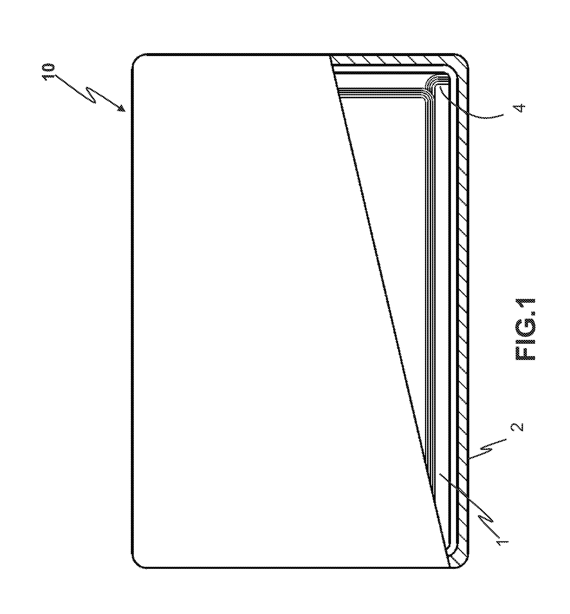
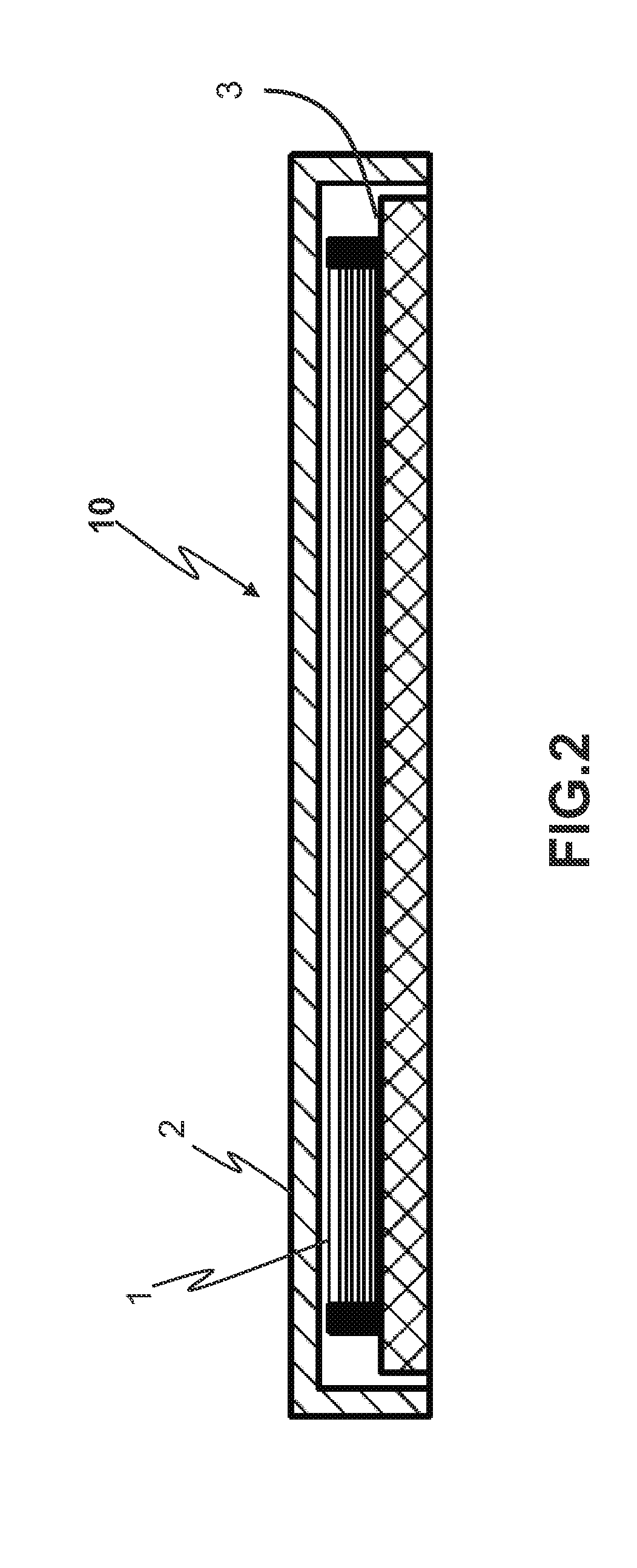
[0032]Referring to FIGS. 1-3 there is disclosed an ultra thin proximity card reader according to one embodiment of the present invention. The ultra thin proximity card reader 10 comprises a pickup coil / antenna 1 and a ferrite plate 3. The ferrite plate 3 is located below the pickup coil / antenna 1 and extends beyond the pickup coil's outside perimeter. The pickup coil / antenna is glued to the ferrite plate to insure a consistent position.

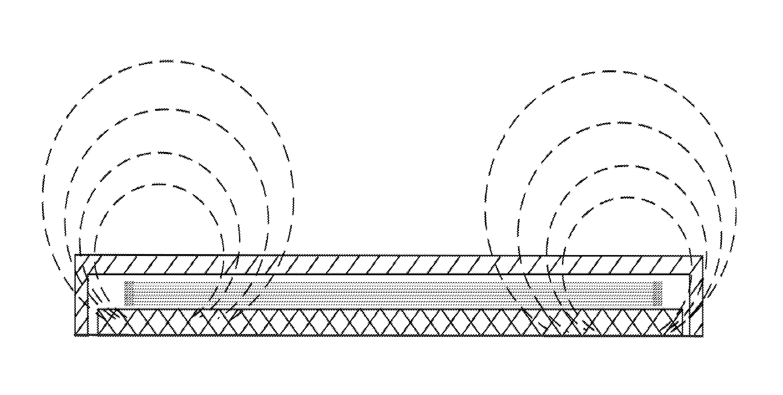
[0033]FIG. 3 illustrates how the magnetic field around the front of the antenna is unimpeded while the ferrite material constrains the field in the rear. This effect essentially creates a directional antenna. In viewing the figure the circular dash lines represent the magnetic field. Herein it is able to extend in an upward direction away from the invention itself. This is in contrast to the bottom portion of the device wherein the field is unable to extend. This not only directs the filed but also serves to strengthen its performance.

[0034]A complete...


PUM

PropertyMeasurementUnit
Frequencyaaaaaaaaaa
Thicknessaaaaaaaaaa
Flexibilityaaaaaaaaaa

Abstract

The proximity readers for opening a door are typically located on a lock, a metal prison wall, on a metal fire door, on a metal door frame. Traditionally, a proximity reader had to be made thick so that the pickup coil / antenna was not close to the metallic mounting surface otherwise the reader's read range would be drastically reduced. The present invention eliminates the problem of these metal surfaces reducing the read range of the proximity reader when mounted on these types of metallic surfaces. The present invention allows the pickup coil / antenna to be mounted close to the metallic mounting surface, be low profile without reducing the read range.

Description

BACKGROUND OF THE INVENTION[0001]1. Field of the Invention[0002]The present invention relates generally to a method of improving a security proximity card reader's performance and construction of an ultra thin proximity card reader and more particularly to a method of constructing an ultra thin reader that can be mounted directly on a metallic surface without reducing its read range.[0003]2. Description of Related Art[0004]A proximity card reader is the mechanism that is placed next to a locked door and serves to unlock said door when a proximity card is held near or passed over the proximity card reader. Data read from the card is then processed by some control device and if authenticated, unlocks the proper door.[0005]A proximity card reader and proximity card communicate with each other through radio frequency fields of typically 125 kHz, or 13.56 MHz or other frequencies if available. The proximity cards have an antenna consisting of a coil of wire, a capacitor, and an integrate...

Claims


Application Information

Patent Timeline
IPC IPC(8): G06K7/10H01Q1/22H01Q7/06
CPCG06K7/10336H01Q1/2216H01Q7/06G06K7/10168Y10T29/49018
Inventor BUCCOLA, CHARLES
Owner BUCCOLA CHARLES
Learn More