Cutting tool

a cutting tool and cutting technology, applied in the field of cutting tools, can solve the problems of increasing the brittleness of a material, insufficient hardness of high-speed steels for an entire series of applications, and the inability to produce suitable carbides, etc., to achieve the effect of increasing the resistance of the cutting tool, enhancing the bonding connection, and facilitating production

Active Publication Date: 2015-03-19
KENNAMETAL INC
View PDF28 Cites 4 Cited by
  • Summary
  • Abstract
  • Description
  • Claims
  • Application Information

AI Technical Summary

Benefits of technology

[0015]The positive-locking connection is more preferably formed as a type of mortise-and-tenon connection between a profiled tenon and a profiled mortise that is complementary to it, wherein more preferably the tool shaft has the profiled tenon. Furthermore, the profiling of the mortise and tenon is particularly designed such that an enlarged contact surface is formed between the tenon and mortise on one hand, at least in relation to a simple V-shaped profile, and the movement in the direction of the center longitudinal axis is blocked by positive engagement on the other hand. While the enlarged contact surface serves to enhance the bonded connection, that is enable soldering over a larger surface for example, increased resistance of the cutting tool to tensile, bending, and torsional forces is achieved through the special positive-locking connection.
[0016]In addition, an embodiment variant is preferred in which the tenon has a T-shaped profile with a top facing toward the mortise and a base facing away from the mortise. The top in this case functions as a type of rear grip element, which engages in the material protrusion extending in the transverse direction with respect to the center longitudinal axis in the mortise, whereby the locking effect is achieved in the direction of the center longitudinal axis of the positive-locking connection. Any T-shaped profile or T-shaped cross-section can be relatively easily produced, for example through milling, based on which the tenon has a type of hammer shape.

Problems solved by technology

The hardness of such types of high-speed steels is insufficient for an entire series of applications however, which is why in such cases it is preferable to use so-called carbides.
However, as the hardness increases, typically the brittleness of a material also increases, which means that suitable carbides are relatively sensitive to impacts or vibrations.
In addition, brittle materials also have the problem of stress effects, because they do not plastically deform when reaching the elasticity limit but instead immediately fracture so to speak.
The problem with cutting tools designed in this manner, however, is the fact that the corresponding solder connections will fracture under higher loads.

Method used


Image

  • Cutting tool
  • Cutting tool
  • Cutting tool

Examples


Embodiment Construction

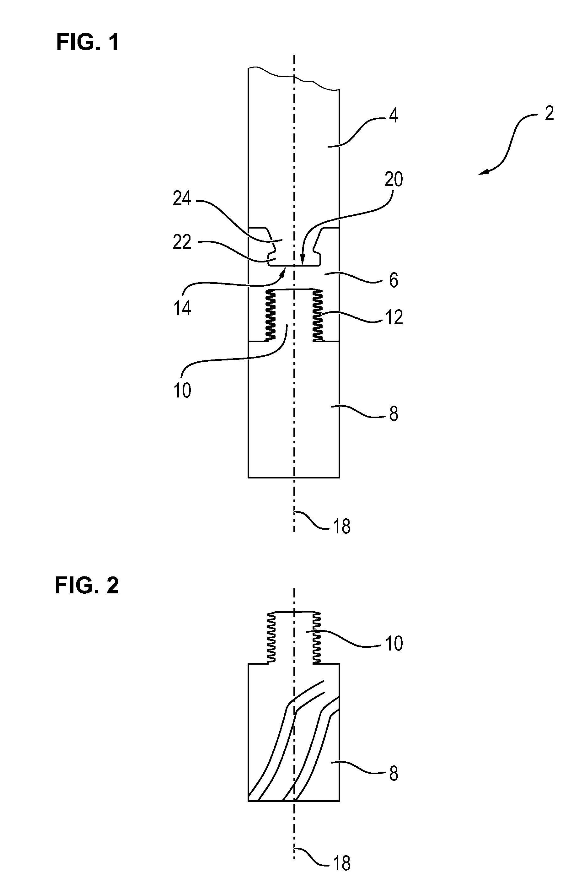
[0038]A cutting tool, described by means of example in the following and shown in FIG. 1, is formed as a multi-piece milling tool 2 and has a tool shaft 4, a coupling element 6, as well as a replaceable milling head 8. In this case, the tool shaft 4 and the replaceable milling head 8 are each produced from carbide, while the coupling element 6 is produced from tool steel.

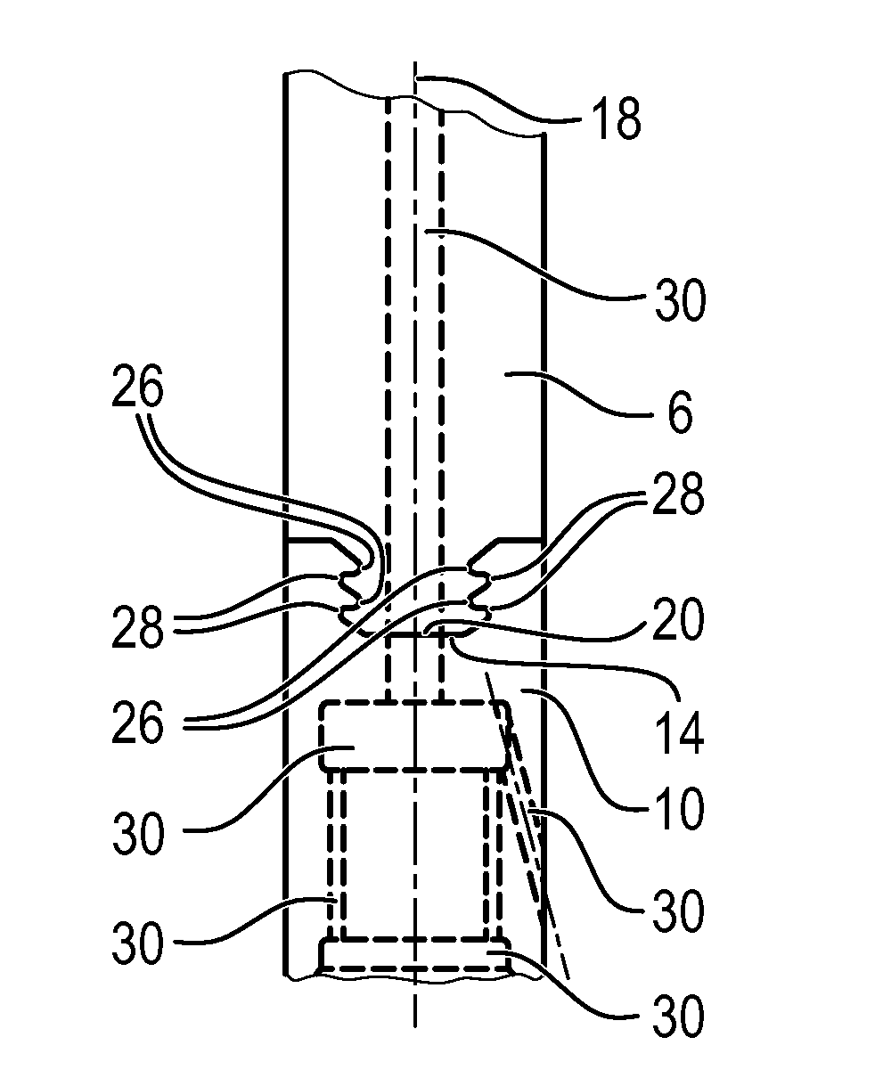
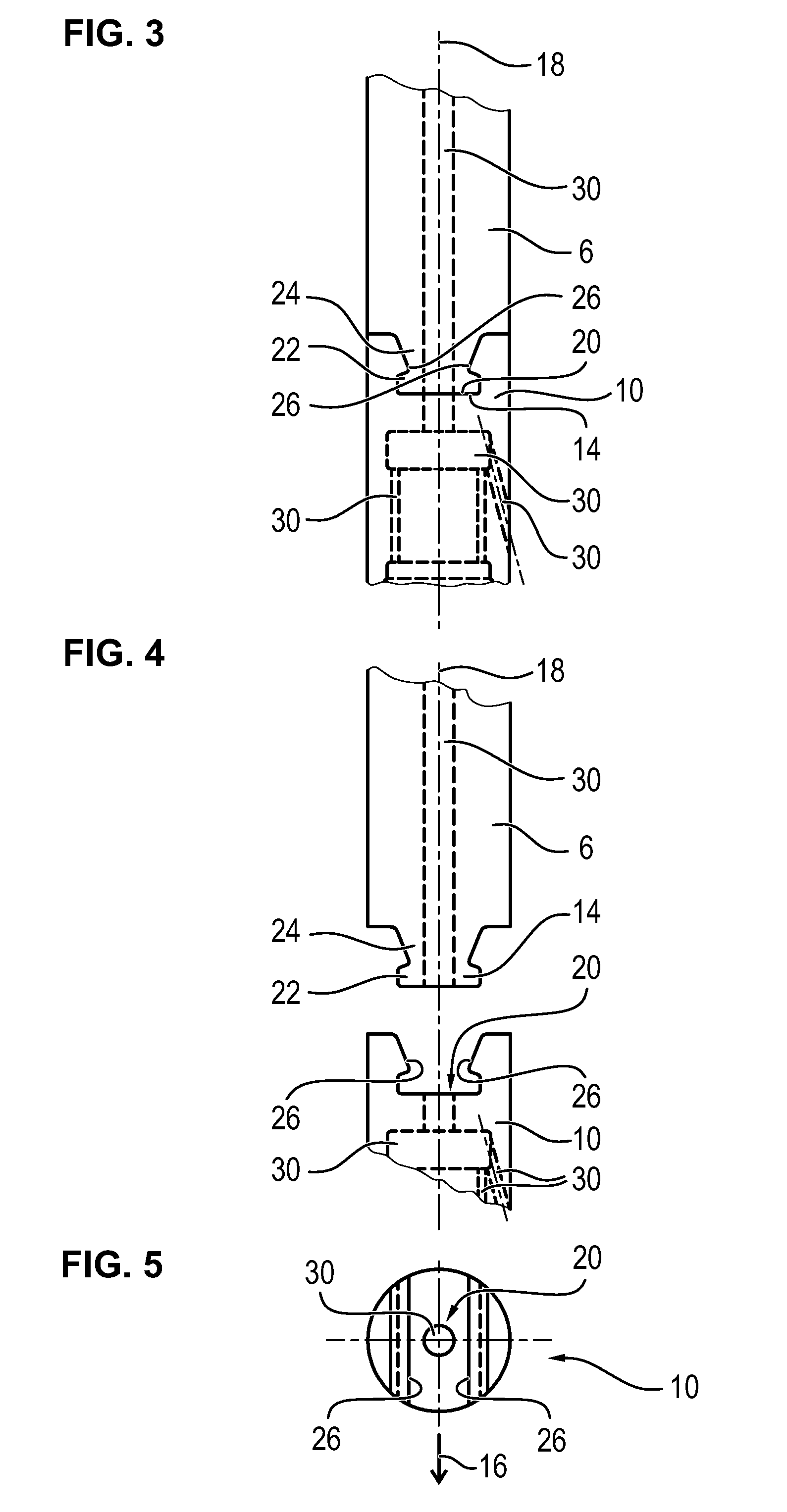
[0039]The coupling element 6 and the replaceable milling head 8 are connected to each other via a threaded connection, which is reversible and detachable, so that essentially various replaceable milling heads 8 can be combined with the coupling element 6, or however the replaceable milling head 8 can simply be replaced if worn. In this case, the replaceable milling head 8, as depicted in FIG. 2, has a threaded pin 10, which is threaded into a recess 12 with a counter-thread to form a threaded connection.

[0040]Contrary to this, the tool shaft 4, which is formed for a tool chuck, which is not shown, of a machine tool,...


PUM


Abstract

The invention relates to a cutting tool, particularly for use in a tool chuck of a machine tool, including a tool shaft with a center longitudinal axis and a tool head. The tool head is connected to the tool shaft via a positive-locking connection, which locks the movement in the direction of the center longitudinal axis and the positive-locking connection is supplemented by a bonded connection, particularly a soldered connection.

Description

BACKGROUND OF THE INVENTION[0001]1. Field of the Invention[0002]The invention relates to a cutting tool, particularly for use in a tool chuck of a machine tool, comprising a tool shaft with a center longitudinal axis and a tool head.[0003]2. Description of Related Art[0004]Cutting or machining tools such as, for example, milling tools or lathe tools, are constructed from multiple parts in some cases and usually comprise a tool shaft and a tool head connected thereto. The tool head in this case is used for the actual machining of workpieces, i.e. to remove material, and accordingly has at least one cutting edge or one cutting insert. The tool shaft, on the other hand, is normally formed for use in a tool chuck of the machine tool and frequently functions additionally as a type of extension so that the tool head can be positioned in the desired location, for example in a recess or borehole.[0005]As a result of this, a cutting tool typically has an elongated shape and is additionally c...

Claims


Application Information

Patent Timeline
Patent Type & Authority Applications(United States)
IPC IPC(8): B23C5/10
CPCB23C5/10B23C2240/00B23C2210/02B23C5/109B23B31/005B23B2240/08B23B2240/11B23B2260/138B23C2240/08B23C2240/24Y10T407/1908B23B29/02
Inventor PFEUFFER, HERR BERND
Owner KENNAMETAL INC
Why Eureka
Try Eureka