Electric spindle for numerical control machines

a numerical control machine and electric spindle technology, applied in the direction of attachment devices, chucks, manufacturing tools, etc., can solve the problems of significant increase in the overall length limited operability of the electric spindle, and machining time and cost. , to achieve the effect of cheap manufacturing

Active Publication Date: 2015-03-19
FCS SYST
View PDF11 Cites 4 Cited by
  • Summary
  • Abstract
  • Description
  • Claims
  • Application Information

AI Technical Summary

Benefits of technology

The aim of this invention is to create an electric spindle that can hold all types of tools, and is also cheap to make.

Problems solved by technology

Although working very well, this type of electric spindle has limited operability, because the maximum rotational speed achievable by the electric spindle is closely conditioned by the structure and overall dimensions of the tool-holder spindle, which in turn are closely connected to the type of tool that the tool-holder spindle is designed to use.
It is evident that these performance limits create major problems when the same numerical control milling machine must be used for mechanical machining that contemplates using, in rapid succession and on the same workpiece, two different types of tool that respectively require high driving torque and low rotational speeds (roughing tools typically require rotational speeds below 20,000 rpm), or low driving torque and high rotational speeds (finishing tools typically require rotational speeds above 20,000 rpm and usually below 50,000 rpm).
In this case, as electric spindles capable of using both types of tool cannot physically be made, when changing from a high-speed tool to a low-speed tool or vice versa, it is necessary to replace the entire electric spindle block mounted on the milling machine en masse, with all of the problems that this entails in terms of machining times and costs.
Even if the tool-change times of the numerical control milling machine are drastically reduced, tool-holder spindles of the disassemblable type have resulted in a significant increase on the overall length of the electric spindle and, even more important, have significantly complicated the structure of the electric spindle.
Despite the drastic reduction in weight with respect to monobloc electric spindles, even the disassemblable tool-holder spindles still have an overall weight of many tens of kilograms, with all of the drawbacks that this entails during the spindle change.

Method used


Image

  • Electric spindle for numerical control machines
  • Electric spindle for numerical control machines
  • Electric spindle for numerical control machines

Examples


Embodiment Construction

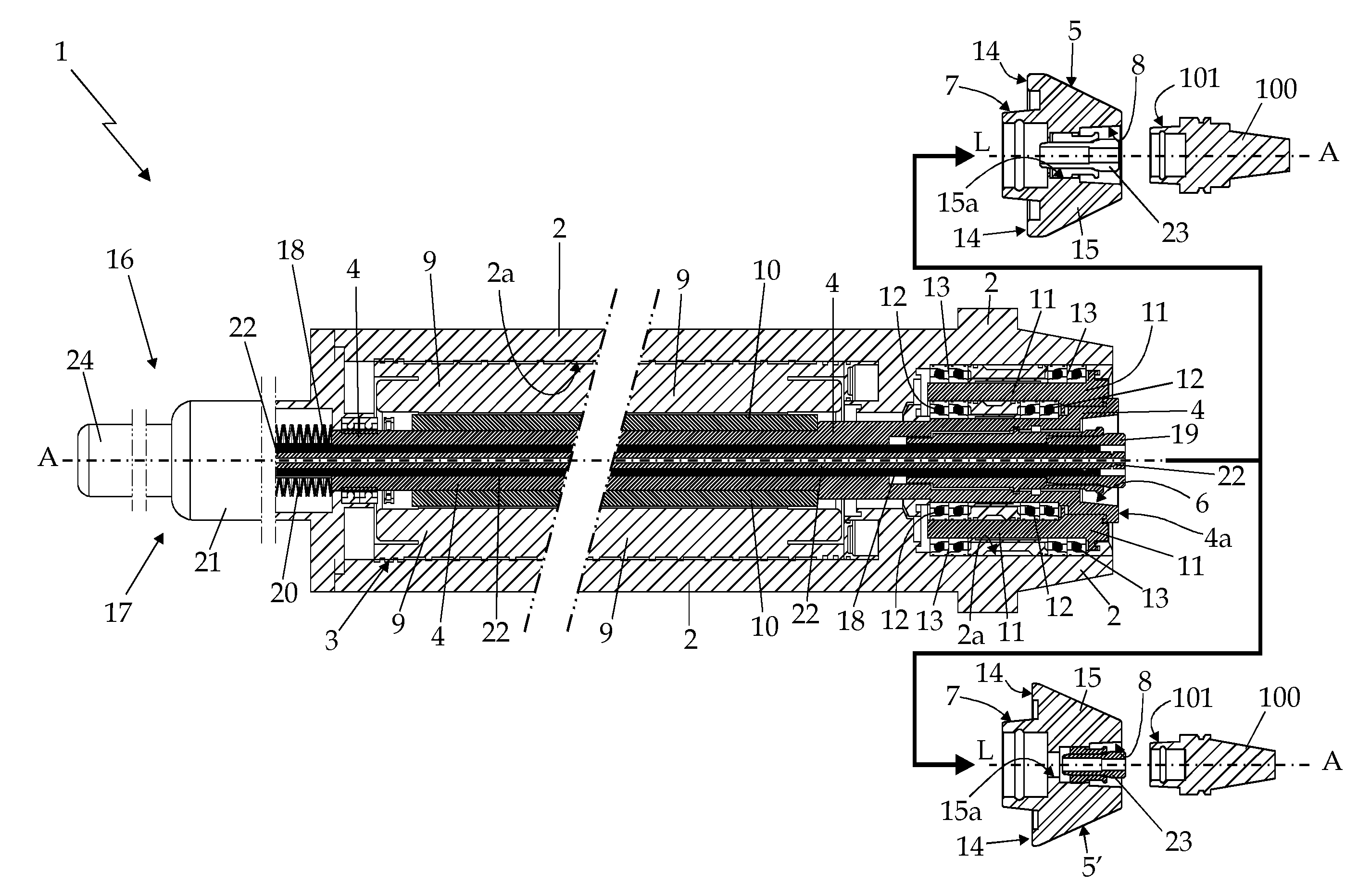
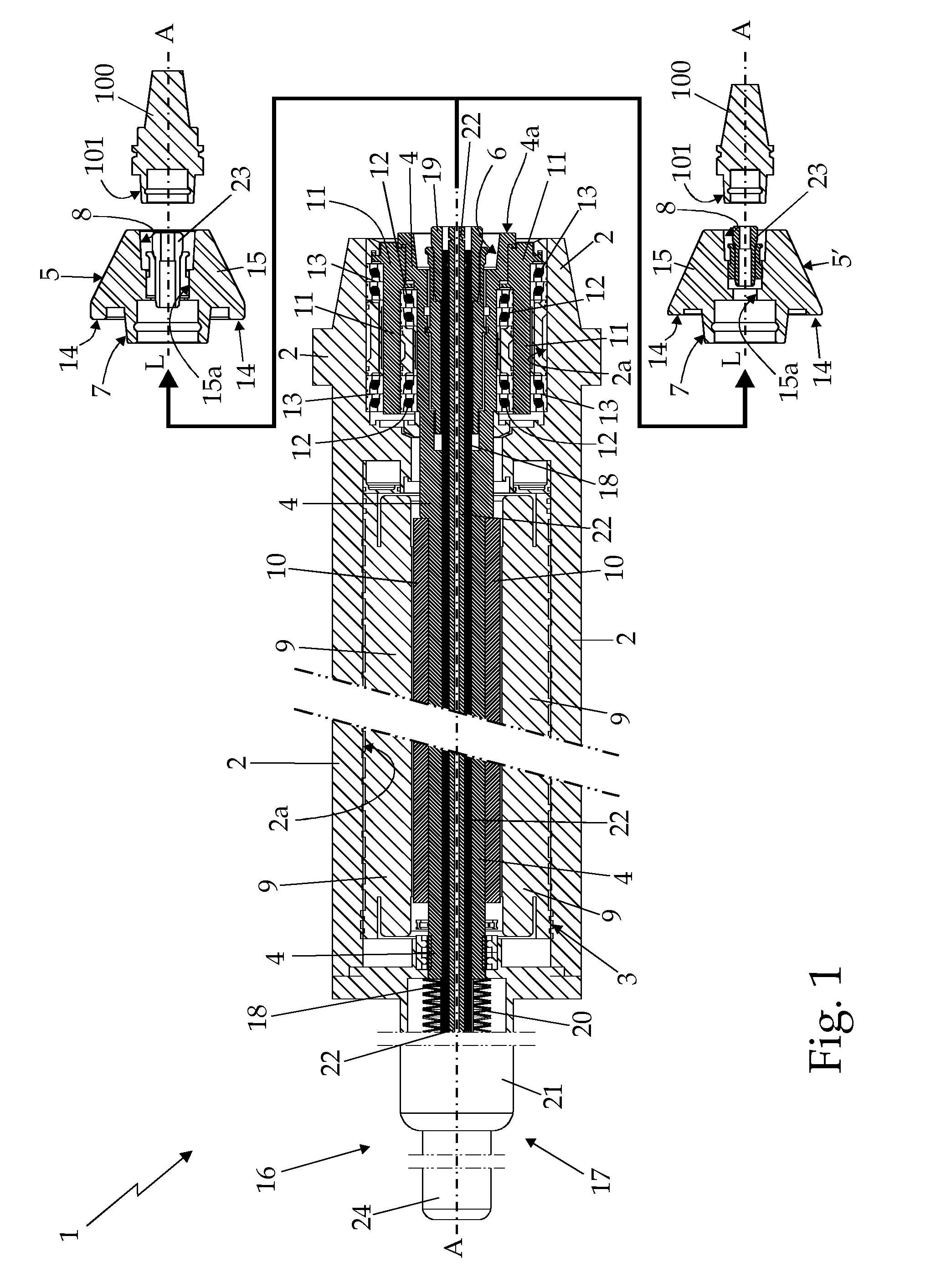
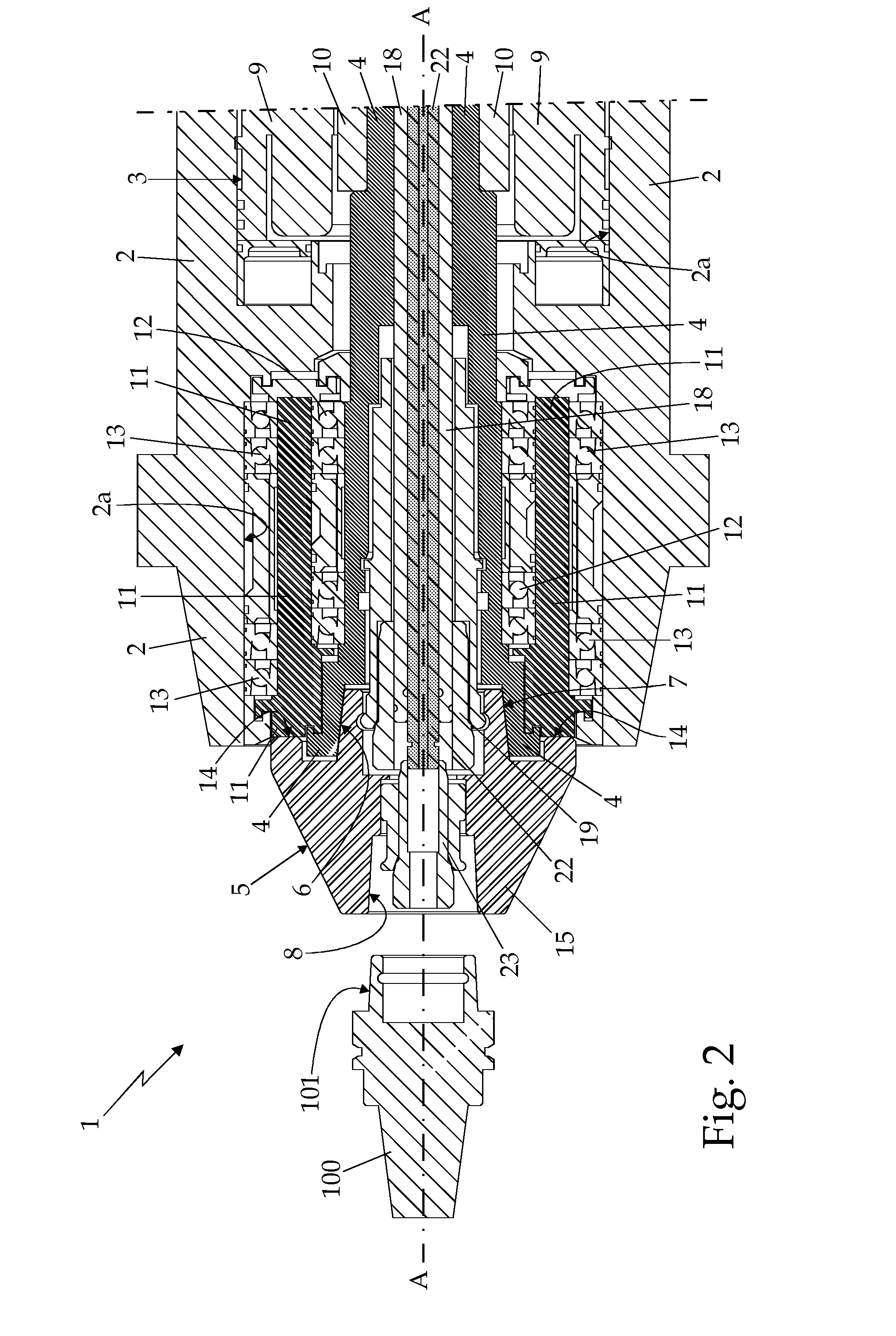
[0023]With reference to FIGS. 1, 2 and 3, reference numeral 1 indicates, as a whole, an electric spindle for numerical control machines, which has a longitudinal reference axis A and is structured to selectively lock and drive into rotation a generic tool 100 while maintaining the tool locally coaxial to the electric spindle axis A. The electric spindle 1 also finds particularly advantageous use in numerical control milling machines.

[0024]The electric spindle 1 is basically made up of an outer structural casing 2 which is structured to be rigidly attachable to the spindle holder carriage or slide (not shown) of any numerical control milling machine or similar; of an electric motor 3 which is stably housed within the structural casing 2, and is provided with a drive shaft 4 which projects / emerges with its front end 4a outside the structural casing 2 while remaining locally coaxial to the electric spindle axis A; and of at least one tool-holder head 5 which is structured to be attacha...


PUM

PropertyMeasurementUnit
nominal diameteraaaaaaaaaa
diameteraaaaaaaaaa
diameteraaaaaaaaaa

Abstract

Electric spindle for numerical control machines structured to lock and rotationally drive a tool about a predetermined reference axis locally coinciding with the longitudinal axis of the tool; the electric spindle comprising: an outer structural casing that is structured to be rigidly attachable to a generic numerical control machine; an electric motor that is housed within the structural casing and is provided with a drive shaft, which projects / emerges with its front end outside the structural casing while remaining locally coaxial to the reference axis of the electric spindle; a rotating thrust-bearing bushing or sleeve, which is fitted in an axially rotatable manner on the front end of the drive shaft via interposition of a first set of annular rolling bearings, and is maintained coaxial to the reference axis of the electric spindle by a second set of annular rolling bearings, which are interposed between the rotating bushing or sleeve and the structural casing; and at least one disassemblable tool-holder head that is structured to be attachable, in a rigid and stable though easily releasable manner, to the front end of the drive shaft, is structured so as to accommodate and retain, in a rigid and stable though easily releasable manner, the shank of a generic tool for numerical control machines, and is provided with a peripheral crown that is dimensioned / structured to stably abut, selectively and alternatively, on the front end of the drive shaft or on the rotating thrust-bearing bushing or sleeve.

Description

RELATED APPLICATION DATA[0001]This application is the national stage entry of International Appl. No. PCT / IB2013 / 053052, filed Apr. 17, 2013, which claims priority to Italian Patent Application No. TV2012A000063, filed Apr. 17, 2012. All claims of priority to these applications are hereby made, and each of these applications is hereby incorporated in its entirety by reference.TECHNICAL FIELD[0002]The present invention relates to an electric spindle for numerical control machines.[0003]More in detail, the present invention relates to an electric spindle for numerical control milling machines, an application to which the following description will make explicit reference, but without any loss of generality.BACKGROUND ART[0004]As is known, the electric spindles of numerical control machines are composed of a tool-holder spindle and an electric motor that are housed inside a same outer structural casing, aligned one after the other along the longitudinal axis of the electric spindle, an...

Claims


Application Information

Patent Timeline
Patent Type & Authority Applications(United States)
IPC IPC(8): B23Q1/70B23C1/02B23Q5/10
CPCB23Q1/70B23Q5/10B23C2260/08B23C2270/022B23C1/02B23Q5/048B23Q2005/005Y10T409/309352Y10T409/309408Y10T409/309464B23Q3/12B23B31/263
Inventor CALZAVARA, ANDREACANUTO, ALMERINO
Owner FCS SYST
Why Eureka
Try Eureka