Supercharge Your Innovation With Domain-Expert AI Agents!

Numeric control machine tool

Active Publication Date: 2015-03-19
PARPAS
View PDF13 Cites 13 Cited by
  • Summary
  • Abstract
  • Description
  • Claims
  • Application Information

AI Technical Summary

Benefits of technology

The patent aims to address the problem of excessive deformation in horizontal main supporting crossmembers in large milling or boring machines without increasing production costs. The technical effect is the elimination or reduction of such problems.

Problems solved by technology

Unfortunately, “gantry” type numeric control milling machines cannot perform mechanical processing with removal of material, which requires precision exceeding one hundredth of a millimetre, unless they have a main supporting crossmember with a largely over-sixed structure with respect to traditional uses, with the considerable increase in costs this involves.
This solution obviously heavily influences the total production costs of the machine.
Unfortunately, however, when the length of the horizontal main supporting crossmember exceeds 4-6 metres and the total weight of the slide and the vertical tower exceeds 2000 Kg, limitation of torsional deformations of the main supporting crossmember becomes technically and economically prohibitive, so the torsional and bending deformations of the crossmember start to negatively influence the degree of precision of positioning of the tool fixed onto the tool-holder head.
This is why large “gantry” type milling and boring machines cannot guarantee, at reasonable costs, the same degree of precision offered by milling or boring machines of smaller dimensions.

Method used


Image

  • Numeric control machine tool
  • Numeric control machine tool
  • Numeric control machine tool

Examples


Embodiment Construction

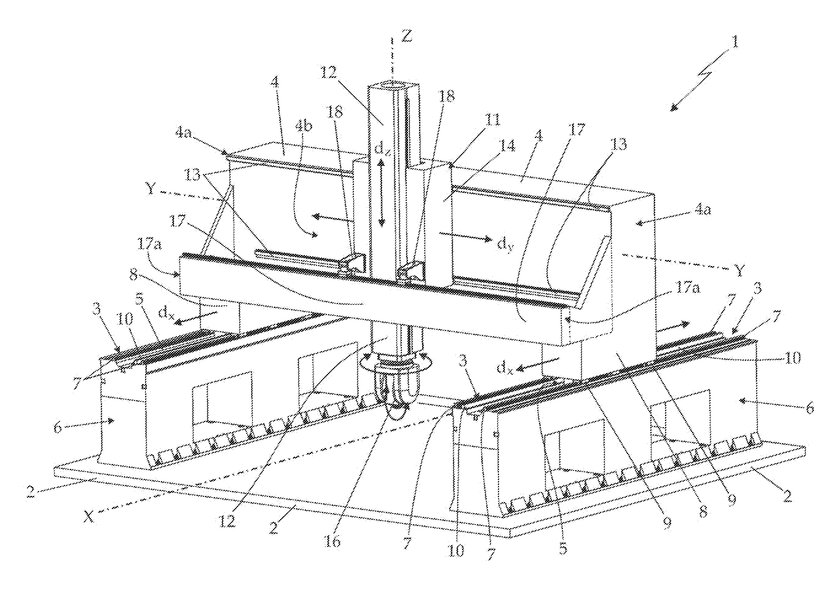
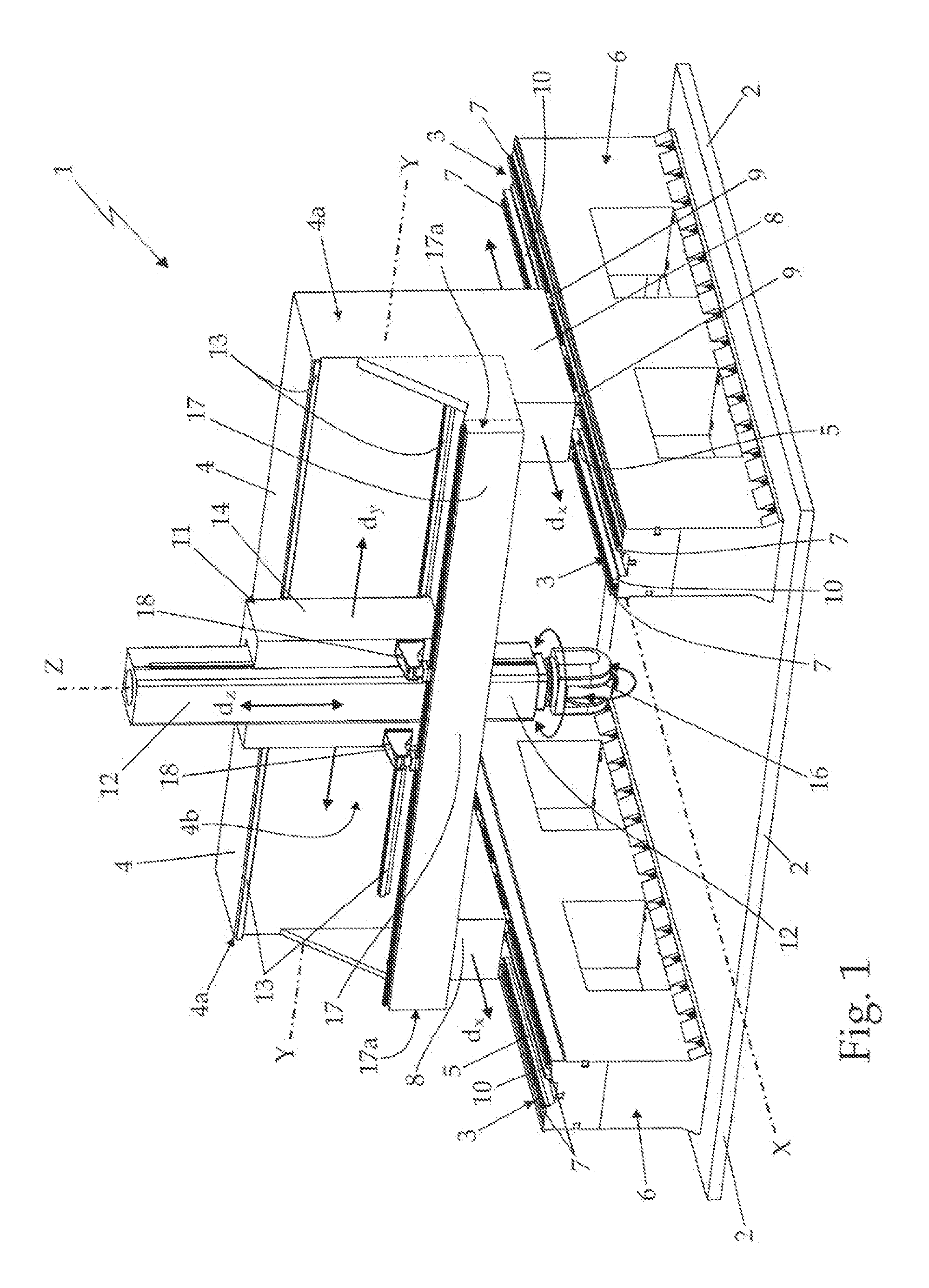
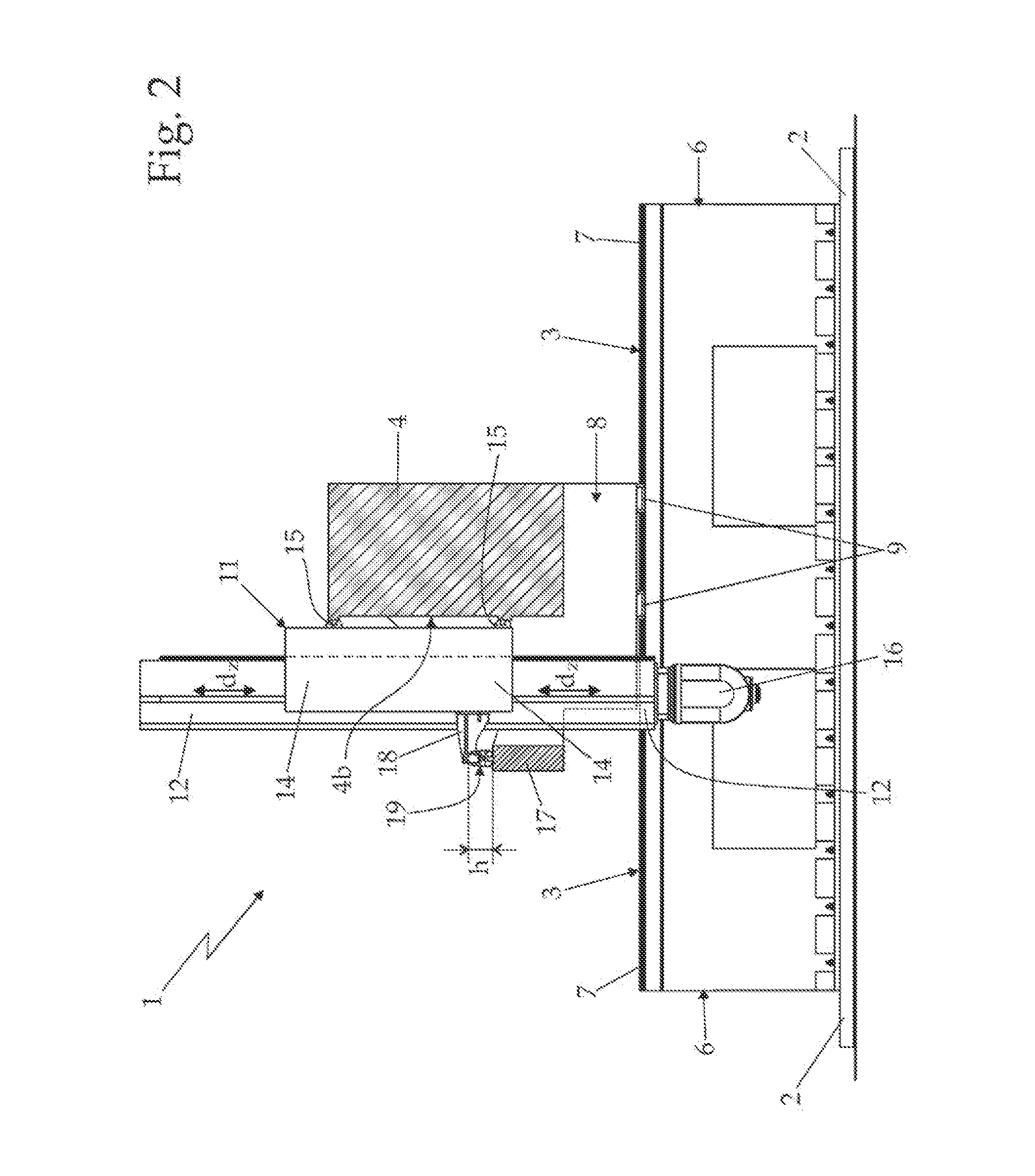
[0015]With reference to FIGS. 1 and 2, the number 1 denotes in its entirety a movable supporting crossmember type numeric control machine-tool, in this case a “gantry” type milling machine or boring machine, which is particularly advantageously used in milling or boring large metal articles.

[0016]The “gantry” type numeric control machine tool 1 essentially comprises: a basement 2 resting on the ground, which is equipped with two longitudinal rectilinear guides 3 which are parallel and alongside each other, which extend on the upper face of the basement 2 at a predetermined' distance from each other, remaining simultaneously parallel to a first reference axis X, substantially horizontal; a rectilinear main supporting crossmember 4 with highly rigid structure and length preferably exceeding 4 metres, which extends above the basement 2, at a predetermined height from the ground, remaining locally parallel to a second reference axis Y, substantially horizontal and locally perpendicular ...


PUM


Abstract

A numeric control machine tool of the type comprising: a basement; a substantially rectilinear main supporting crossmember which extends above the basement and has two axial ends structured so as to rest stably and in an axially sliding manner on two reciprocally parallel rectilinear guides present on the basement; a movable slide which is fixed protruding onto a side of the main supporting crossmember, with the possibility of moving along the body of the main supporting crossmember; a substantially rectilinear vertical movable tower, which is fixed on the movable slide in a substantially vertical position and with the possibility of translating with respect to the movable slide in a vertical direction; and a tool-hold head which is fixed on the lower end of said vertical movable tower; the main supporting crossmember being structured so as stably to support the weight of the movable slide, the vertical movable tower and the tool-holder head, and the numeric control machine tool also comprising a substantially rectilinear auxiliary supporting crossmember, which extends beside the main supporting crossmember so as to be locally facing and distanced from the side of the crossmember which supports the movable slide; and on which the movable slide rests by means of interposition of a reaction member which is structured so as to vary its height, simultaneously exercising an upward thrust on the projecting arm.

Description

TECHNICAL FIELD[0001]The present invention relates to a numeric control machine tool.[0002]In greater detail, the present invention relates to a numeric control milling machine of the movable portal type, to which the explanation below shall specifically refer without thus losing its general nature.BACKGROUND ART[0003]As known, numeric control milling machines or boring machines, traditionally called “gantry” type, essentially comprise a long horizontal main supporting crossmember with a highly rigid structure, which extends horizontally and perpendicularly to the longitudinal axis of the machine, at a predetermined height from the ground, and has two axial ends structured so as to rest stably and in an axially sliding manner on two horizontal rectilinear guides which extend parallel to the longitudinal axis of the machine, on the top of two side walls or buttresses raised from the basement; a movable slide which is fixed protrudingly and in an axially sliding manner on a series of ...

Claims


Application Information

Patent Timeline
IPC IPC(8): G05B19/19
CPCG05B19/195G05B2219/49001G05B2219/50264B23C1/002B23Q1/012B23Q11/0014
Inventor FRASCATI, CARLOPARPAJOLA, VLADI
Owner PARPAS
Features
  • R&D
  • Intellectual Property
  • Life Sciences
  • Materials
  • Tech Scout
  • Unparalleled Data Quality
  • Higher Quality Content
  • 60% Fewer Hallucinations
Learn More