Wellbore encasement

a wellbore and wellbore technology, applied in the field of wellbore encasement, can solve the problems of gas bubbles entering cement, horizon catastrophe, and catastrophe, and achieve the effect of less rotation and faster material deposition

Inactive Publication Date: 2015-03-26
PRITCHARD MICHAEL
View PDF6 Cites 45 Cited by
  • Summary
  • Abstract
  • Description
  • Claims
  • Application Information

AI Technical Summary

Benefits of technology

[0041]The device may include multiple printheads positioned at regular circumferential intervals, so providing faster deposition of materials and requiring less rotation of the device about the longitudinal axis of the wellbore for lining an entire circumference of the wellbore.

Problems solved by technology

However, as is well documented, a single flaw in that seal, perhaps a crack the size of a human hair, can be enough to cause a catastrophic leak.
One known failure mechanism, suspected of being the cause of the Deepwater Horizon catastrophe, is gas bubbles getting into the cement and forming channels for pressurised gas or oil to surge uncontrollably up the well.
As illustrated by reference to FIG. 2, another known cause for inadequate cementing is because of the non-uniformity of the borehole walls.
This can be problematic if the borehole wall includes voids or fissures, increasing the volume of the annulus over that expected such that the predetermined volume of cement would not reach the desired specific height.
A problem encountered in depositing cement in the annular gap between the casing and the wellbore surface is that residual drilling mud and mud filtrate cake can be stuck to the casing and formation which reduces cement bonding effectiveness.
Another problem encountered in wellbore cementing is centralising the wellbore casing.
If the centraliser is not strong enough to centre the pipe, or if it breaks, the consequences can be very expensive.
If it breaks in a deviated well, centralisation is usually completely lost, rendering effective cementation impossible.
Furthermore, the centraliser may jam the pipe down hole.
Rather than being at risk of high pressure fluids escaping through a casing, the walls of water well boreholes may be liable to inward collapse.

Method used


Image

  • Wellbore encasement
  • Wellbore encasement
  • Wellbore encasement

Examples


Embodiment Construction

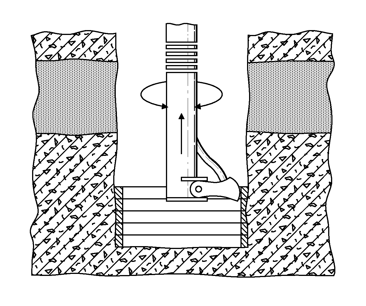
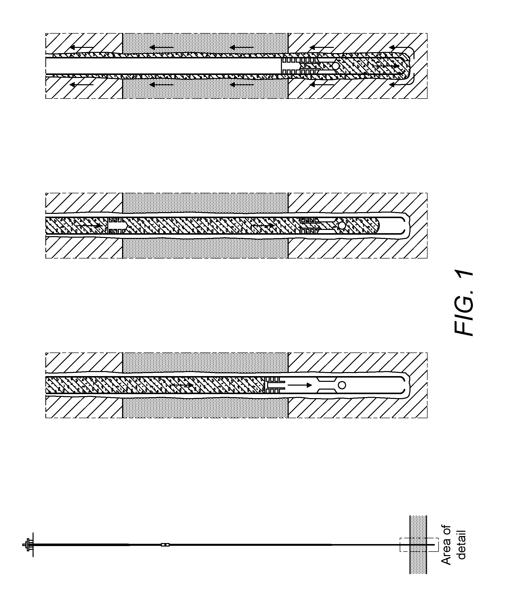
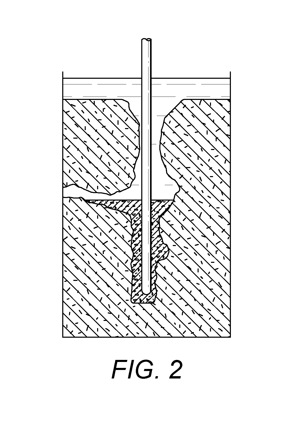
[0060]In simple terms, the invention relates to the concept of depositing lining material to wellbores using 3D printing technology. A media dispensing apparatus including at least one nozzle is inserted down a borehole for depositing multiple layers of lining material to the interior surface of the borehole in a controlled manner. One embodiment is shown in FIGS. 5 and 8, in which the nozzle is mounted via a universal joint to a distal end of a hollow support rod. The support rod contains a primary flexible conduit for fluidly connecting the nozzle with a source of a first lining material. The support rod further contains a secondary flexible conduit for fluidly connecting the nozzle with a source of a second lining material, different to the first. As shown in FIG. 6, the nozzle and the conduits may be arranged to dispense the first and second materials simultaneously, in a form of extrusion. In other embodiments, only a single source of material is connected to the nozzle.

[0061]I...


PUM


Abstract

A method of encasing a wellbore is provided comprising the application of 3D printing technology to apply a series of layers of lining material to the interior surface of a wellbore. The layers may be of different materials to make best use of their different material properties, to provide structural integrity and good sealing properties, for example. Through suitable printhead control, specific structural features such as channels for receiving measurement, power or communications equipment may be incorporated into the lining structure. Associated devices for depositing the layers of lining material are also provided.

Description

FIELD OF THE INVENTION[0001]The present invention relates to the encasement of wellbores, and in particular to methods of depositing cement into an annulus between a newly-drilled borehole and reinforcing casing within the borehole.BACKGROUND TO THE INVENTION[0002]Conventionally, newly-drilled boreholes are reinforced by the insertion therein of a casing, which may comprise steel or concrete pipes, to provide structural integrity to the wellbore. Such casings are typically slightly smaller in diameter than the drill string and are secured in place by pumping cement into the annulus formed between the outer surface of the casing and the borehole.[0003]As illustrated by reference to FIG. 1, cementing is usually performed by circulating a cement slurry through the inside of the casing and out into the annulus through a casing shoe at the bottom of a casing string. In order to deposit a correct quantity of the cement slurry on the outside of the casing, a plug is pumped with a displacem...

Claims


Application Information

Patent Timeline
Patent Type & Authority Applications(United States)
IPC IPC(8): E21B33/13E21B33/14E21B41/00E21B33/138
CPCE21B33/13E21B41/0078E21B33/14E21B33/138B33Y10/00E21B41/00
Inventor PRITCHARD, MICHAEL
Owner PRITCHARD MICHAEL
Why Eureka
Try Eureka