System and method for attenuation correction of phantom images

a technology of attenuation correction and phantom image, which is applied in the field of medical imaging, can solve the problems of easy attenuation, difficult to obtain reliable ac of pet signals based on mr signals from a single scan, and inconvenient correction of mr image data for attenuated pet image data,

Active Publication Date: 2015-04-02
GENERAL ELECTRIC CO
View PDF3 Cites 8 Cited by
  • Summary
  • Abstract
  • Description
  • Claims
  • Application Information

AI Technical Summary

Problems solved by technology

One challenge in obtaining desired PET image quality is that gamma rays, in the energy spectrum produced by positron-electron interactions, are easily attenuated by typical body tissues and are differently attenuated by different body tissues.
However, because MR signals do not attenuate in the same way as PET or CT signals attenuate, and because MR signal return is highly dependent on the type of pulse sequence used (with each pulse sequence emphasizing a different material, whereas the PET signal is attenuated by every material intervening between a recombination event and a pair of detectors), it becomes difficult to obtain reliable AC of the PET signals based on MR signals from a single scan.
Essentially, the MR image data is not useful for correcting the attenuated PET image data.
Moreover, a schedule of MR pulse sequences, optimized for clinical scans (patient body materials) may not reliably return a usable image from a standard PET phantom.
Manual positioning of phantoms, or registration of an attenuation map with acquired data, however, is extremely difficult to accomplish with the precision needed for accurate AC.
This problem is generalizable to clinical practice: Standard phantoms do not have the identically non-uniform distribution of tissue as is found in a patient.
As such, attenuation of a phantom scan is not expected to accurately map to a subsequent patient scan, and phantom-based AC is not implemented using the same protocol as would be used in clinical settings for a patient scan.
The fluid body within a PET phantom can, however, exhibit MR image distortion for various reasons.
Additionally, some phantoms are filled with a semi-solid gel, which may not return a quality MR image.
Other problems with implementing this approach relate to the material specificity of MR pulse sequences.

Method used


Image

  • System and method for attenuation correction of phantom images
  • System and method for attenuation correction of phantom images
  • System and method for attenuation correction of phantom images

Examples


Embodiment Construction

[0023]Reference will be made below in detail to exemplary embodiments of the invention, examples of which are illustrated in the accompanying drawings. Wherever possible, the same reference characters used throughout the drawings refer to the same or like parts, without duplicative description. Exemplary embodiments of the present invention are described with respect to imaging a commercially-available phantom (i.e. a body of known shape and composition, usable for scan calibration, or the like), however, embodiments of the invention also are applicable for imaging any target for which a template image and attenuation map can be obtained. Embodiments of the invention relate to improving attenuation correction of PET phantom images.

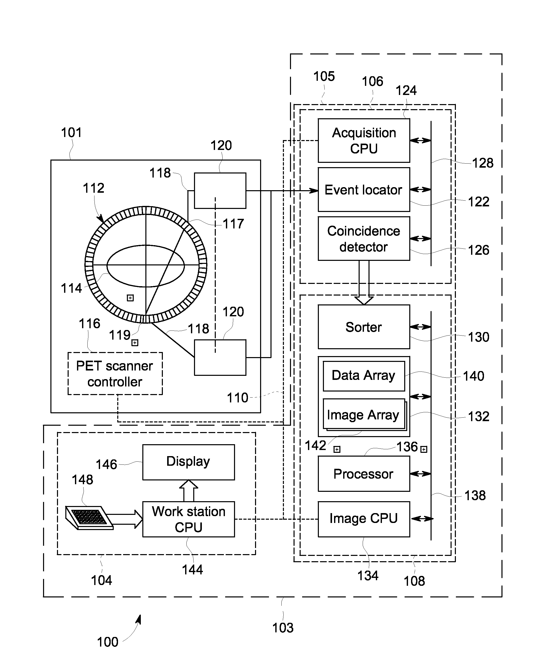
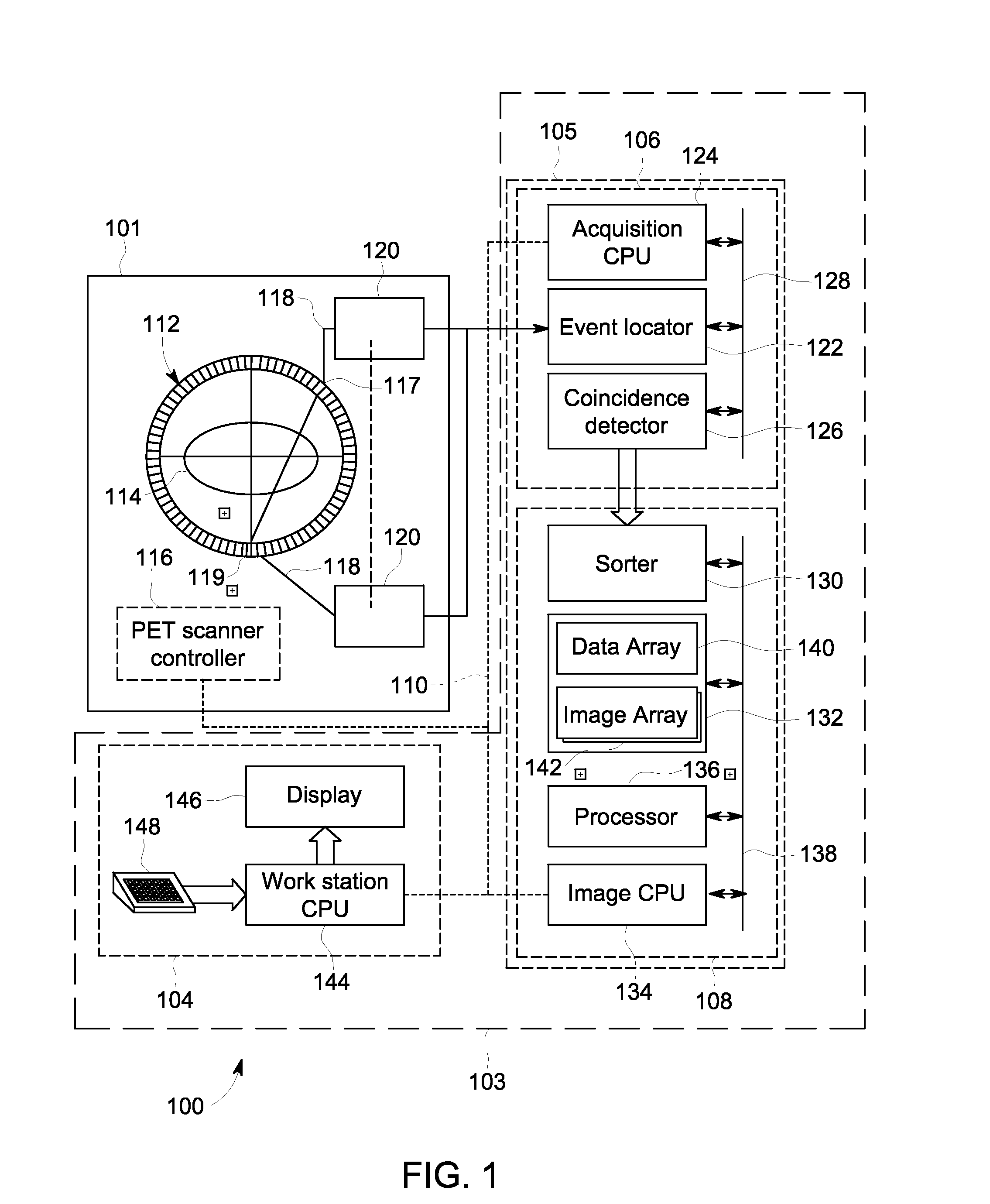
[0024]FIG. 1 shows in schematic view an exemplary embodiment of a PET imaging system 100 in which various embodiments of the invention may be implemented. Many other types of PET imaging system are known, and the exemplary PET system 100 is merely one type...


PUM


Abstract

A method for attenuation correction of a phantom image in a PET imaging system includes obtaining raw scan data of a scanned phantom, a non attenuation corrected template image of a stock phantom of like type to the scanned phantom, and an attenuation map of the stock phantom. The method further includes generating a non-attenuation corrected raw image of the scanned phantom based on the raw scan data, registering the template image and attenuation map to the raw image through a rigid image transform, and applying the registered attenuation map to the raw scan data to enable reconstruction of an attenuation corrected final image.

Description

BACKGROUND[0001]1. Technical Field[0002]Embodiments of the invention relate generally to system and method for medical imaging. Particular embodiments relate to systems and methods for attenuation correction of combined positron emission tomography / magnetic resonance imaging (“PET-MR”).[0003]2. Discussion of Art[0004]Positron emission tomography (“PET”) machines use one or more rings of scintillators or other detectors to generate electrical signals from gamma rays (photon pairs) that produced from the recombination of electrons, within a target material, and positrons, emitted from decay of a radionuclide packaged in a tracer compound. Typically, recombination events occur within about 1 mm from the radionuclide decay event, and the recombination photons are emitted in generally opposite directions to arrive at different detectors. Paired photon arrivals that occur within a detection window (usually less than a few nanoseconds apart) are counted as indicating a recombination event,...

Claims


Application Information

Patent Timeline
Patent Type & Authority Applications(United States)
IPC IPC(8): G01T1/29G06T5/50G06T7/00G06T3/00
CPCG01T1/2985G06T3/0068G06T5/50G06T2207/30004G06T2207/10104G06T2207/20048G06T7/0024A61B6/037A61B5/0035A61B5/055A61B6/4275A61B6/4417A61B6/5205A61B6/5247A61B6/5258A61B6/583G01T1/169
Inventor DELLER, TIMOTHY WAYNESPOHN, MICHAEL LEEAMBWANI, SONAL
Owner GENERAL ELECTRIC CO
Why Eureka
Try Eureka