Mechanized slot drilling

a slot drilling and slot technology, applied in the direction of shaft sinking, shaft equipment, borehole/well accessories, etc., can solve the problem of limited net energy that can be transmitted to the cutting formation, and achieve the effect of maximizing rotation, enhancing or replacing, and rapid creation of slot volum

Inactive Publication Date: 2015-04-09
SHELL OIL CO
View PDF3 Cites 13 Cited by
  • Summary
  • Abstract
  • Description
  • Claims
  • Application Information

AI Technical Summary

Benefits of technology

[0012]The method and apparatus of the present invention may provide more energy to be converted to mechanical motion within the wellbore to enable more rapid creation of slot volume than a system that requires mechanical motion be provided from the surface facilities by reciprocating a cutting element.
[0013]This rotating cutting action may be provided from the electric motors within the wellbores, or could be enhanced or replaced by rotating the entire drilling assembly up to the max torque allowed by the pipe having strength similar to wellbore tubular used in conventional directional drilling. Pipe rotation is induced to the entire drill string from the rotary table of the rig and drilling trajectory is planned to maximize the rotation (therefore resulting cutting action) while minimizing bend curvature and concentration of torque and bending moment in the drill pipe assembly.

Problems solved by technology

Hydrocarbons trapped in such formations then migrate toward the volume connected to the wellbore at rates that can result in economic production of the hydrocarbons from formations that were previously considered to be uneconomic to produce.
The net energy that can be transmitted to cutting formation is limited by the strengths of the cutting cables and the speed with which surface rigs are able to reciprocate the cutting cables.

Method used


Image

  • Mechanized slot drilling
  • Mechanized slot drilling
  • Mechanized slot drilling

Examples


Embodiment Construction

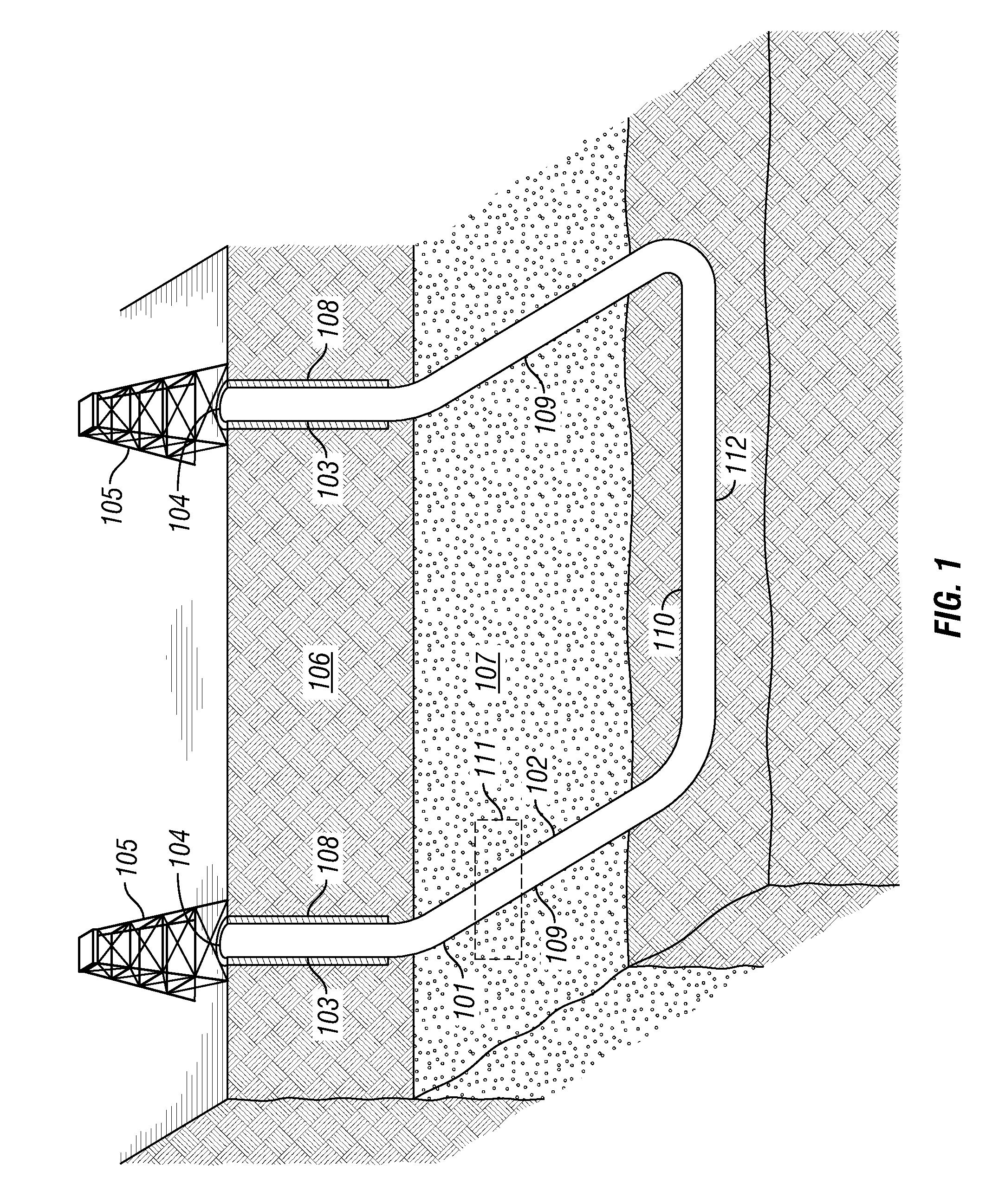
[0019]Referring now to FIG. 1, a wellbore 101 with a horizontal U-shaped section 102 is shown. The wellbore has substantially vertical sections 103 extending from surface locations 104 where drilling rigs 105 are placed. The vertical sections extend through overburden 106 and into a target formation 107 that could contain hydrocarbons such as, for example, natural gas. The sections of the wellbores that extend through the overburden may be cased with casings 108 that are cemented into place. The U-shaped section 102 preferably has two essentially parallel legs 109, connected by an essentially horizontal run 110. In some embodiments, the legs 109 could be tilted up, so that any hydrocarbon liquids produced from the wellbore after the well is completed would flow down to a point close to the vertical sections where they could be produced, by for example, an electrical submersible pump. Tilting up of the legs 109 may also facilitate the removal of cuttings as the slot is formed since t...


PUM


Abstract

A system and method are provided for providing access to surfaces within a formation is provided, the method including: providing a wellbore from a first surface location to a second surface location; inserting into the wellbore a cylindrical cutting assembly connected to at least two wellbore tubulars, one of the wellbore tubular extending to each of the first surface location and the second surface location; and rotating the radial cylindrical cutting element.

Description

RELATED APPLICATIONS[0001]This application claims the benefit of U.S. Provisional Application No. 61 / 866,400 filed Aug. 15, 2013, which is incorporated herein by reference.FIELD OF THE INVENTION[0002]The inventions relates to systems and methods for providing plane opening in formations.BACKGROUND TO THE INVENTION[0003]Considerable amounts of natural gas have been found to be producible from formations such as source rocks, shale, and other low porosity and permeability formations by drilling long horizontal wells and stimulating the wells with multiple propped fractures so that a large volume of formation within a short distance of the well is connected to the wellbore. Hydrocarbons trapped in such formations then migrate toward the volume connected to the wellbore at rates that can result in economic production of the hydrocarbons from formations that were previously considered to be uneconomic to produce. Although fracturing of the formations can result in profitable production, ...

Claims


Application Information

Patent Timeline
Patent Type & Authority Applications(United States)
IPC IPC(8): E21B43/25E21B7/28E21B7/00E21B4/04E21B4/16
CPCE21B43/25E21B4/04E21B7/28E21B7/001E21B4/16E21B7/00E21B11/06E21B43/305
Inventor FONSECA OCAMPOS, ERNESTO RAFAELMACDONALD, DUNCAN CHARLESCHACIN, FRANCISCO JOSEDOBROSKOK, ANASTASIALIU, YINGHUIMOWAD, BENJAMINDYKSTRA, MARK WILLIAM
Owner SHELL OIL CO
Why Eureka
Try Eureka