Unlock instant, AI-driven research and patent intelligence for your innovation.

Communication protocol

a technology of communication protocol and high voltage, applied in the direction of power conversion system, oscillation generator, pulse technique, etc., can solve the problems of difficulty, significant device failure risk, and the inability of switching devices in the system to easily fail, so as to achieve the effect of reducing size, cost and/or complexity

Active Publication Date: 2015-04-09
MASCHFAB REINHAUSEN GEBR SCHEUBECK GMBH & CO KG
View PDF8 Cites 14 Cited by
  • Summary
  • Abstract
  • Description
  • Claims
  • Application Information

AI Technical Summary

Benefits of technology

The patent text describes a method for adding sensing and monitoring capabilities to a power switching apparatus without requiring additional communication means or size, cost, or complexity. The method involves modifying the existing device driver or driver controller of the apparatus by fitting a sensing circuit and a modulation circuit, or a demodulation circuit, to provide new functionality. This allows the device driver or controller to communicate with the existing system without needing any additional communication means. The sensed data, such as temperature of the high voltage switching device, is embedded within the existing acknowledgement signal and can be detected by the modified controller or driver. This method can be used to retrofit existing power switching apparatuses or devices without affecting their existing function.

Problems solved by technology

Controlling the switching of such devices presents particular problems, because the electrical environment is relatively noisy, the operating conditions such as load currents and temperatures are continuously changing, and because the voltages / currents being switched are large, leading to a significant risk of device failure.
Moreover when one device in such a system fails, other switching devices in the system can easily fail as a consequence.
Nevertheless, difficulties remain even when a series connection of IGBTs is used, for example in relation to reliability as indicated above.
This may result in disadvantages as indicated above, for example low reliability due to poor voltage sharing among different series-connected power switching devices, e.g., in one or more halves of a phase leg.

Method used


Image

  • Communication protocol
  • Communication protocol
  • Communication protocol

Examples


Embodiment Construction

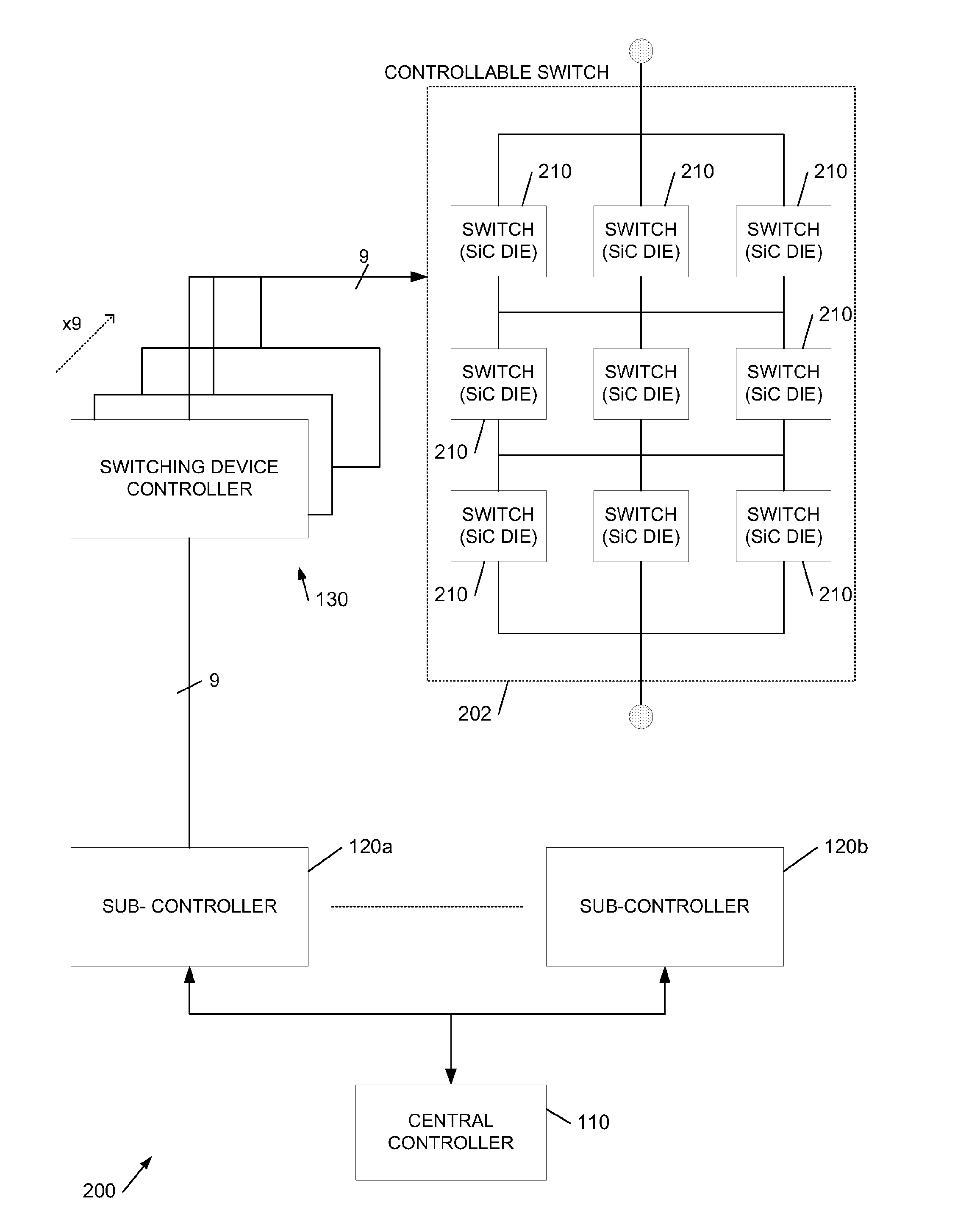
[0043]FIG. 2a shows an embodiment of a power switching apparatus 4, e.g., an inverter, which comprises on the device side one or more power switching devices 5a, 5b coupled to be controlled by respective device drivers in the form of gate drivers 2. The device drivers are coupled to be controlled by at least one driver controller on the control side, for example gate driver controller 1.

[0044]The power switching devices 5a, 5b of FIG. 2a are shown as IGBTs, however may additionally or alternatively comprise one or more FETs (e.g., MOSFETS or JFETs), LILETs, SCRs, etc. Each such device 5a, 5b is shown as having an optional freewheel diode connected in parallel, for protection of the switching device against reverse voltages and currents.

[0045]Coupling between each device driver and its corresponding driver controller preferably provides voltage isolation for example by means of transformer- or opto-coupling. Thus, each bi-directional link 3 of FIG. 2a may comprise optical fibre (e.g....


PUM


Abstract

The application generally relates to apparatus for driving high voltage power switching devices such as IGBTs. An aspect provides a method of adding a sensing capability to a device driver for driving at least one high voltage power switching device of a power switching apparatus having device side circuitry comprising said at least one device and said driver and having control side circuitry comprising a driver controller, the device driver arranged to be coupled to a said driver controller by a communications link, the device driver arranged to drive said at least one device on or off in response to a switching signal received on said communications link from the driver controller, the device driver further arranged to transmit an acknowledge signal to said driver controller in response to said received switching signal, said acknowledge signal detectable at said driver controller as a valid said acknowledge signal, the method comprising: providing a sense circuit to output an indication of a condition of said device side circuitry; providing a modulation circuit to modulate a said acknowledge signal dependent on said condition indication prior to said transmission such that said modulated acknowledge signal is said acknowledge signal to be transmitted by said device driver to said driver controller in response to said received switching signal and detectable at said driver controller as a valid said acknowledge signal.

Description

FIELD OF THE INVENTION[0001]This invention generally relates to apparatus for driving high voltage power switching devices such as IGBTs, and particularly to a method of adding a sensing capability to a device driver for driving at least one high voltage power switching device, a method of adding a monitoring capability to a driver controller for controlling a device driver to drive at least one high voltage power switching device, a method of adding sensing and monitoring capability to a power switching apparatus comprising a driver controller and a device driver, a device driver for driving at least one high voltage power switching device, a driver controller for controlling a device driver to drive at least one high voltage power switching device, a power switching apparatus comprising at least one high voltage power switching device, more particularly to an inverter.BACKGROUND TO THE INVENTION[0002]Power semiconductor switching devices are widely in use for a large range of powe...

Claims


Application Information

Patent Timeline
Patent Type & Authority Applications(United States)
IPC IPC(8): H03K17/18H02M7/537H02M1/08
CPCH03K17/18H02M7/537H02M1/08
Inventor CRONIN, IVAN
Owner MASCHFAB REINHAUSEN GEBR SCHEUBECK GMBH & CO KG