Endosseous implant and method for production thereof

a technology of endoscopy and endoscopy, which is applied in the field of endoscopy implants, can solve the problems of micro cracks under the machined surface, long trial duration, and inapplicability of material removal techniques,

Inactive Publication Date: 2015-04-09
ZDA ZIRCONIA DEVEMENT & APPL
View PDF4 Cites 5 Cited by
  • Summary
  • Abstract
  • Description
  • Claims
  • Application Information

AI Technical Summary

Benefits of technology

[0035]Advantageously, the conicity of the threading of the implantable surface in the cortical bone lies between 0.02 and 0.1. This low conicity makes it possible to ensure a radial maintaining of the implant over all its implantation length in the cortical bone.
[0036]Advantageously, the thread of the cone-shaped threading is interrupted at each turn. This provision prevents bacteria, following the surface of the thread, of penetrating deeply in the tissue implantation.
[0037]Advantageously, the thread interruption surface comprises a cutting edge. Thus, the part of the implant implantable in the cortical bone is self-tapping, taking advantage of the ceramic nature, thus very hard, of the implant.

Problems solved by technology

In addition to the fact that the techniques using material removal are hardly applicable to an implant made of a very hard ceramic material, in particular because of the lack of ductility of such a material which does not allow the formation of a chip by plastic flow of the material; the surface texture is very dependent on the nature of the process and on the material-process couple.
These trials are long lasting, expensive and once the conditions appearing to be optimal are obtained, it still remains to determine the parameters of the surface treatment to control so that the result is reproducible within the framework of a production, more particularly in mass production.
Using such a laser ablation on a ceramic material is, first of all, difficult because of the high temperature resistance of the ceramic material, and furthermore might result in micro cracks formation under the machined surface.
This method is expensive and not suitable for a mass production.

Method used


Image

  • Endosseous implant and method for production thereof
  • Endosseous implant and method for production thereof
  • Endosseous implant and method for production thereof

Examples


Embodiment Construction

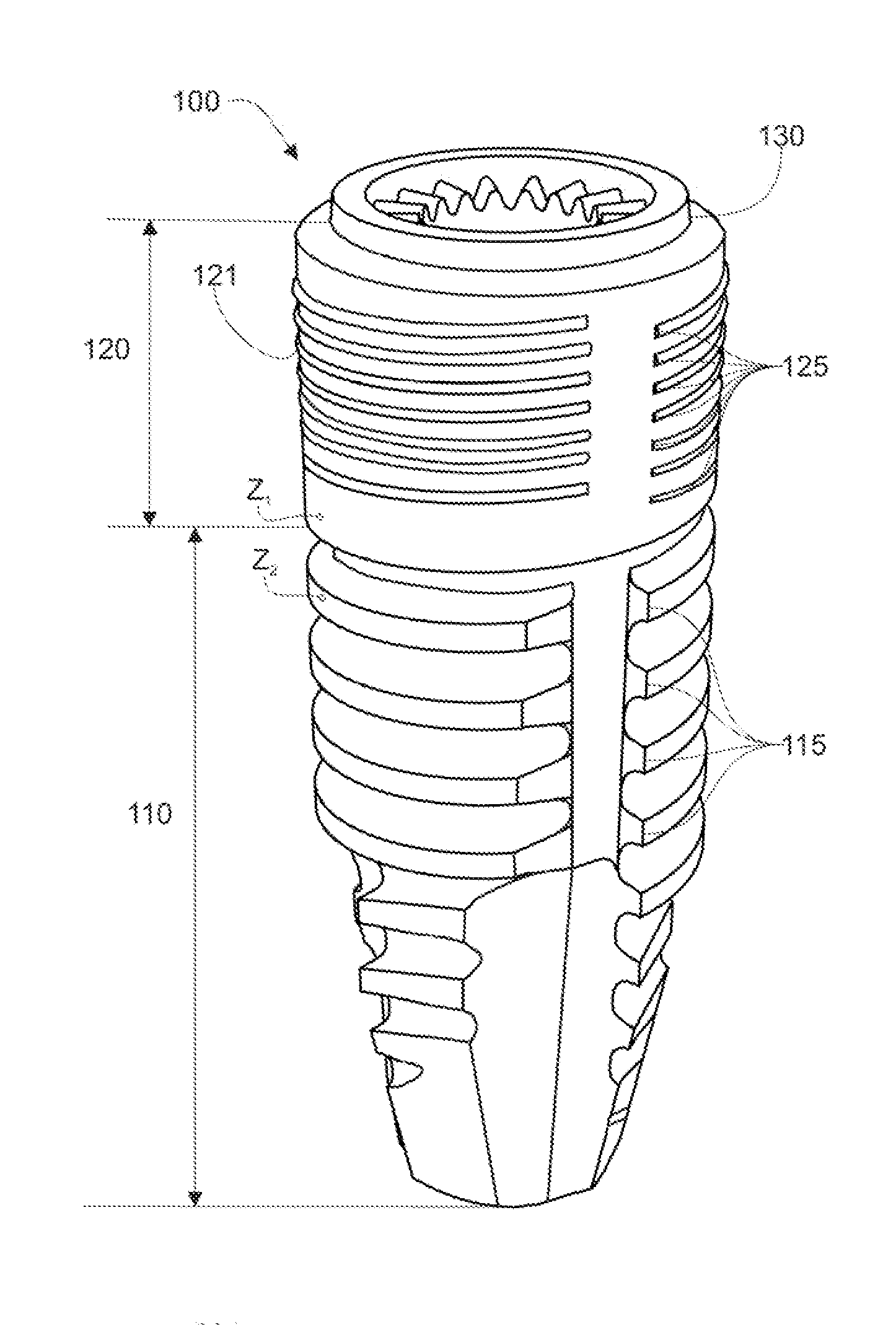
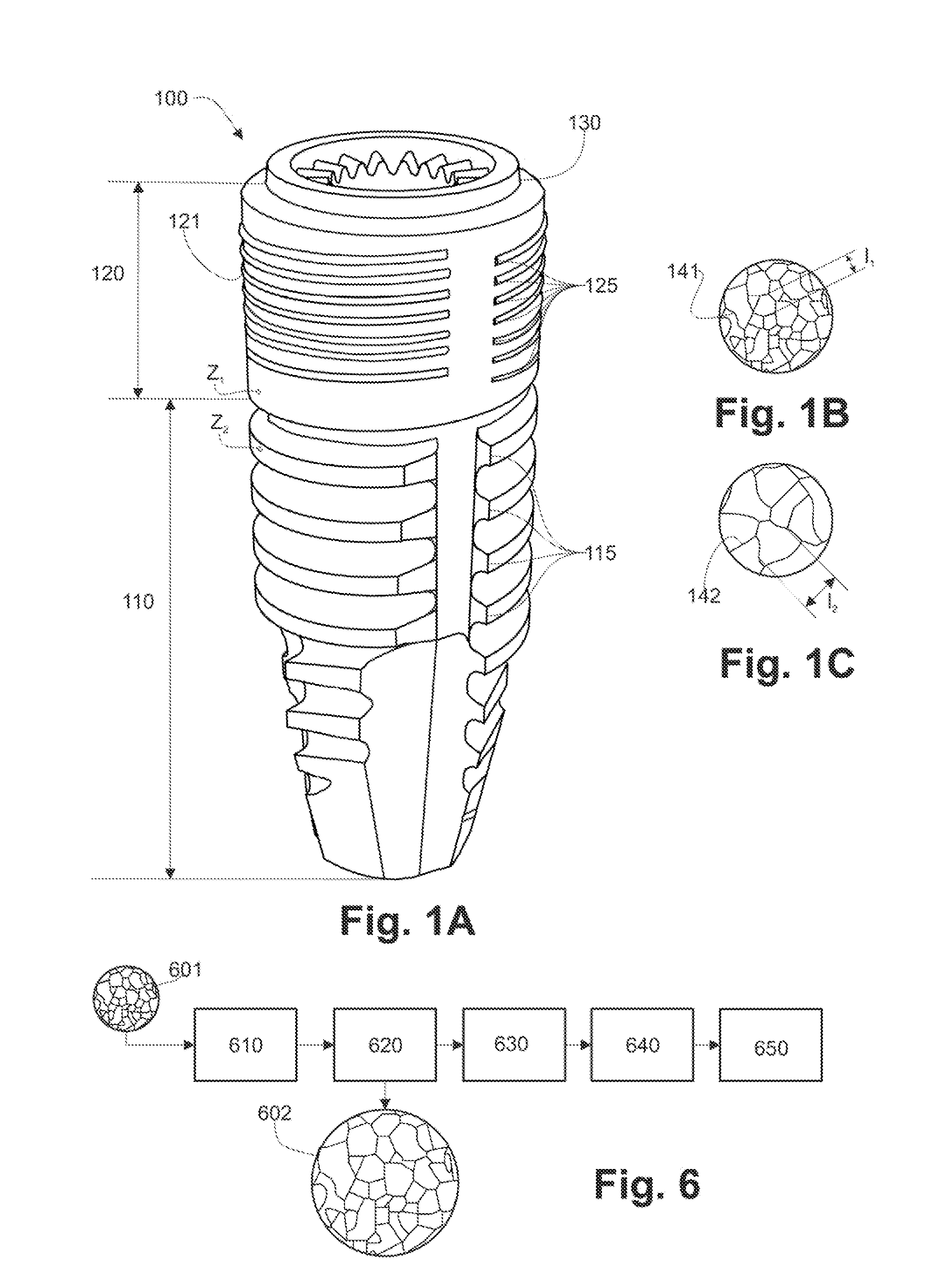
[0047]FIG. 1, according to an example embodiment of an implant (100) according of the invention, more particularly suitable for a periodontal implantation, this one comprises an appreciably cylindrical body, whose surface in contact with the recipients tissues comprises three longitudinal sections.

[0048]A first section (110) suitable for an implantation in the alveolar bone, comprises a threading with a broad pitch. This threading is interrupted at each turn and each interruption of this thread defines a cutting edge (115). A second section (120) suitable for an implantation in the cortical bone comprises a cone-shaped micro-threading (121), said micro-threading being also interrupted at each turn, each interruption constituting a cutting edge (125). Finally, a third section (130) suitable for being implanted in the gum.

[0049]As seen in FIG. 1C, the surface of the first section (110), further designated as the first surface, comprises a surface texture consisting of alveolar cavitie...


PUM


Abstract

An endosseous implant for an implantation in a periodontal tissue made of a sintered ceramic material. The first surface of the implant is configured to be implanted in an alveolar bone tissue. The first surface texture has patterns of recessed alveolar cavities with a closed outline whose average width lies between 8 μm and 15 μm and a surface finish lying between 1 μm and 3 μm. The second surface of the implant is configured to be implanted in a cortical bone tissue. The second surface texture has a pattern of recessed alveolar cavities with a closed outline whose width lies between 1.5 μm and 5 μm and a surface finish lying between 0.1 μm and 0.5 μm. The first and second textures replicate surface texture of tissues similar to the implantation alveolar bone tissue and implantation cortical bone tissue, respectively.

Description

RELATED APPLICATIONS[0001]This application is a continuation-in-part of co-pending U.S. application Ser. No. 13 / 512,410 filed Sep. 24, 2012, which is a §371 application from PCT / EP2010 / 068431 filed Nov. 29, 2010, which claims priority from French Patent Application No. 0958461 filed Nov. 27, 2009, French Application No. 0959327 filed Dec. 21, 2009 and French Application No. 1059598 filed Nov. 22, 2010, each of which is herein incorporated by reference in its entirety.TECHNICAL FIELD OF THE INVENTION[0002]The invention relates to an endosseous implant made of ceramics for medical or veterinary applications. More particularly the invention relates to such a nonmetal implant, preferentially made of a ceramic material.BACKGROUND OF THE INVENTION[0003]Endosseous implants known from prior art, in particular those for a periodontal implantation, consist of metallic materials, generally containing titanium. These prior art implants are subjected to various surface treatments aiming at confe...

Claims


Application Information

Patent Timeline
Patent Type & Authority Applications(United States)
IPC IPC(8): A61C8/00
CPCA61C8/0024A61C2008/0046A61C8/0037A61C8/0012
Inventor GOURLAOUEN-PREISSLER, JEANNINEBUSSON, BERTRAND
Owner ZDA ZIRCONIA DEVEMENT & APPL
Why Eureka
Try Eureka