Processing data from a distributed fibre-optic interferometric sensor system

a technology of interferometer and sensor system, applied in the direction of amplifiers, transmission, geological measurements, etc., can solve the problems of difficult and expensive to completely isolate the reference sensor from fluctuations in environmental parameters, and achieve the effect of reducing nois

Active Publication Date: 2015-04-09
OPTOPLAN
View PDF3 Cites 17 Cited by
  • Summary
  • Abstract
  • Description
  • Claims
  • Application Information

AI Technical Summary

Benefits of technology

[0008]An objective of an embodiment of the present invention is to reduce noise in the distributed fibre-optic interferometric sensor system, such as interferometric and rec

Problems solved by technology

However, it is challenging and expensive to completely isolate the reference sensors fr

Method used


Image

  • Processing data from a distributed fibre-optic interferometric sensor system
  • Processing data from a distributed fibre-optic interferometric sensor system
  • Processing data from a distributed fibre-optic interferometric sensor system

Examples


example 1

Weighted Mean With Time Varying Weighing Functions

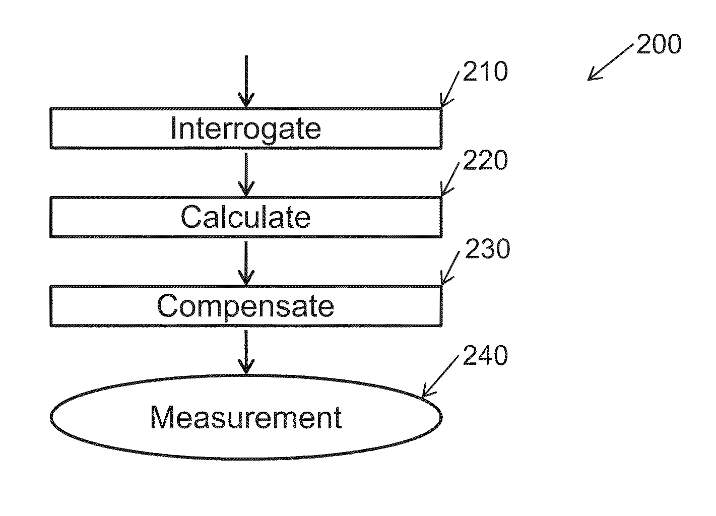
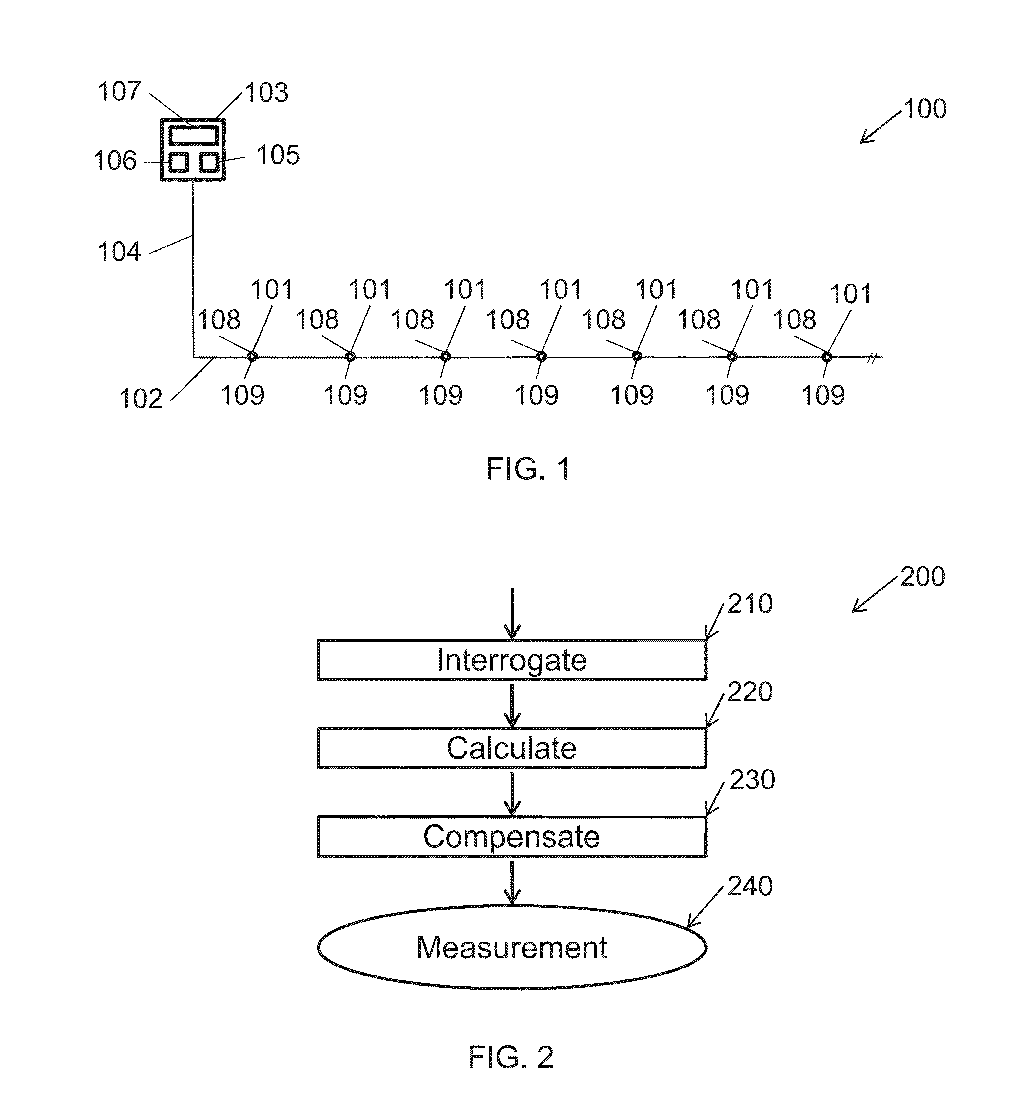
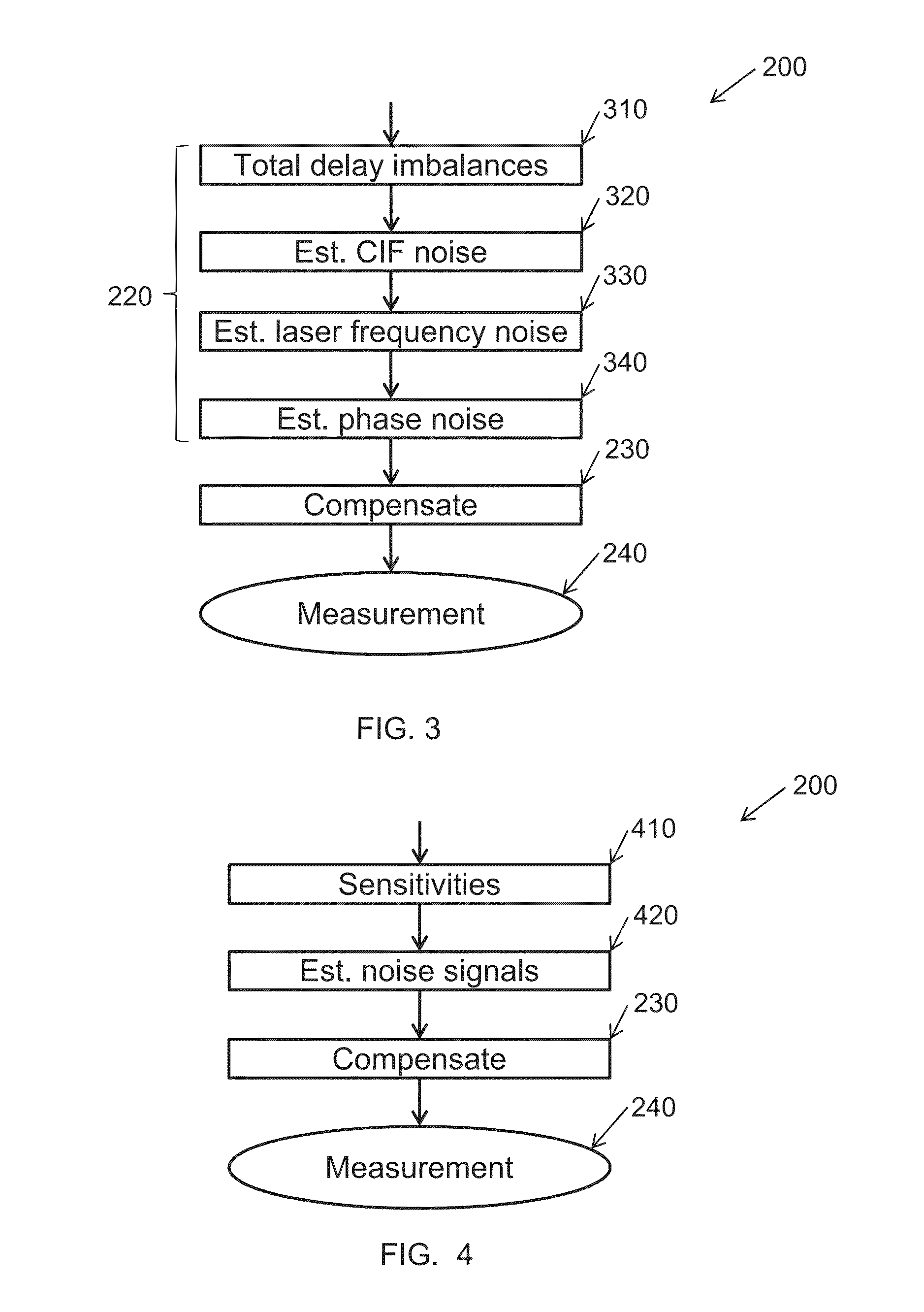
[0070]In this example suitable for a sub-sea seismic sensor system, the method is implemented using these steps for each seismic shot:[0071]1. Subtract a linear bias trend from each raw measurement time series of the reference sensors (“reference trace”), defined as a straight line from the first to the last data point recorded for the current seismic shot.[0072]2. Calculate a square envelope trace for each reference trace, i.e. corresponding to each reference sensor:[0073]a. Apply a bandpass filter with low frequency cut-off and high frequency to the reference trace.[0074]b. Square the filtered reference trace.[0075]c. Convolve the squared trace with a suitable impulse response to obtain the square envelope.[0076]3. Calculate a time varying weight corresponding to each reference trace / reference sensor as the inverse of the square envelope found in the previous step.[0077]4. Calculate the common reference time series for each point i...


PUM


Abstract

A method of processing data from a distributed fibre-optic interferometric sensor system for measuring a measurand, the system comprising multiple interferometric sensors. The method comprises interrogating two or more of the multiple interferometric sensors to record a raw measurement time series for each of the sensors. The method further comprises calculating a common reference time series as a measure of central tendency of the raw measurement time series from two or more reference sensors, the reference sensors being selected from the multiple interferometric sensors. Finally, the method comprises compensating at least one raw measurement time series from a measurement sensor selected from the multiple interferometric sensors with the common reference time series to produce a compensated measurement time series, the measurement sensor being configured to be sensitive to the measurand. The invention further relates to a distributed fibre-optic interferometric sensor system.

Description

PRIOR APPLICATION DATA[0001]The present application claims benefit from European Patent Application 13187914.0 filed on Oct. 9, 2013, incorporated by reference herein in its entirety.[0002]FIELD OF THE INVENTION[0003]The present invention relates to acquisition of data from a distributed fibre-optic interferometric sensor systems. In particular, the invention relates to a method of processing data from such systems.BACKGROUND OF THE INVENTION[0004]Seismic sensor systems commonly comprise large arrays of fibre-optic interferometric sensors, such as hydrophones and optionally accelerometers.[0005]From U.S. Pat. No. 7,245,382 it is known that fibre-optic interferometric sensors which are co-located with a reference device such that optical parameters extracted from the reference signal may be used to correct parameters extracted from a sensor signal. In that way, fluctuations in interrogating laser frequency and fluctuations in delay of compensating interferometers (where such are used...

Claims


Application Information

Patent Timeline
IPC IPC(8): G01B9/02G01V1/00
CPCG01B9/02075G01V1/00G01B9/0207G01H9/004G01D5/35335G01D5/35387G01D5/3539G01V1/186G01B9/02056
Inventor RONNEKLEIV, ERLENDWAAGAARD, OLE HENRIK
Owner OPTOPLAN
Why Eureka
Try Eureka