Pedestal-Mounted Ultrasonic Welding Device

Inactive Publication Date: 2015-04-23
RINCO ULTRASONICS USA
View PDF3 Cites 11 Cited by
  • Summary
  • Abstract
  • Description
  • Claims
  • Application Information

AI Technical Summary

Benefits of technology

[0014]Actuation of each carriage may be through the pressurization of the fluidic muscles, which in turn causes cyclic expansion of the chamber of each muscle, which is accompanied by linear contraction along its length. The contraction of each fluidic muscle causes simultaneous converging translation of the first and second mounting members relative to the linear rail, to cause engagement of a surface of the anvil with a surface of the sonotrode. Synchronizing the electrical power for the stack to correspond to this period of engagement, permits sealing of pouches, which move along a conveyor or a rotary dial, while they are positioned between

Problems solved by technology

Advanced ultrasonic welding components of our co-pending application Ser. No. 12/925,652 are readily incorporated into the design of new form-fill-seal machines, bu

Method used


Image

  • Pedestal-Mounted Ultrasonic Welding Device
  • Pedestal-Mounted Ultrasonic Welding Device
  • Pedestal-Mounted Ultrasonic Welding Device

Examples


first embodiment

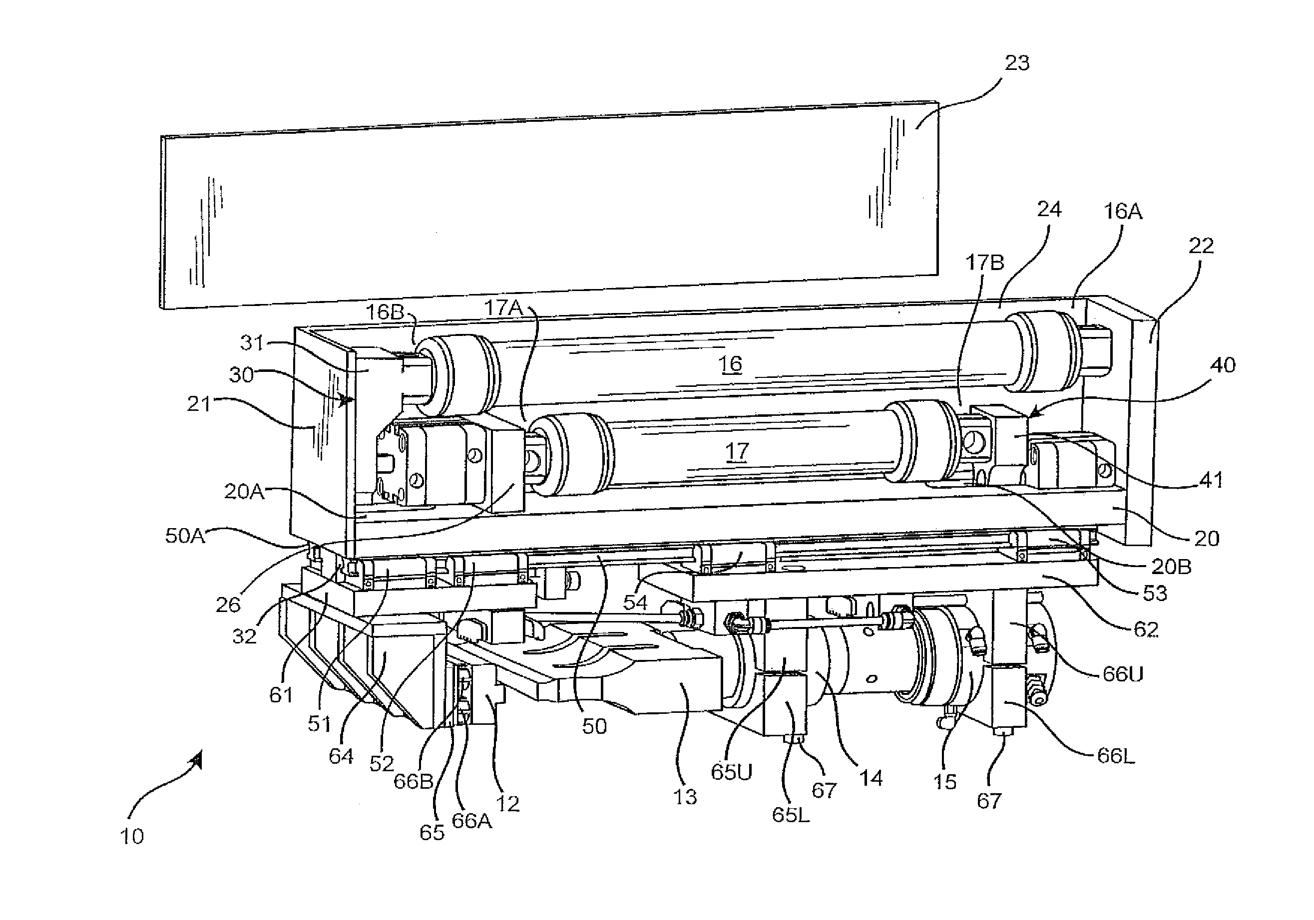
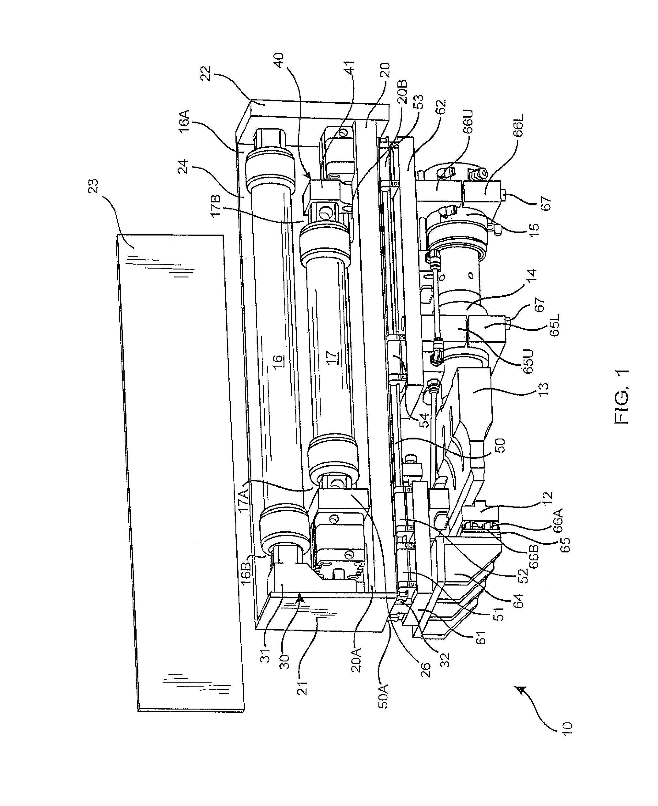
[0069]FIG. 1 shows a perspective view of the retrofit kit 10 of the present invention, which elegantly overcame these obstacles, being shown with a housing side panel 23 removed to expose the actuation portion of the invention.

[0070]The device utilizes a pair of fluidic mechanical muscles in a specially created dual linear mechanism for simultaneous actuation of both the anvil and the horn / booster / converter stack. Today's “Fluidic Muscle,” as it is commonly termed (along with pneumatic artificial muscle), is in part the progeny of an invention by Richard Gaylord. Gaylord, in 1955, received U.S. Pat. No. 2,844,126 for a “Fluid Actuated Motor System and Stroking Device.” In general, a fluidic muscle may be constructed by wrapping a synthetic or natural rubber tube with a woven sheath. This forms an expansible chamber. When a pressurized fluid is applied to the chamber of the fluidic muscle, the chamber expands radially and is accompanied by a corresponding contraction in its length, r...

second embodiment

[0085]Inline positioning of the same fluidic muscles 18 / 19 may be accomplished, as seen in FIGS. 3A and 7 for this second embodiment, by providing a clearance hole 36 in the first mounting member 35 to permit sliding of the first mounting member relative to the fluidic muscle 19 without any contact occurring therebetween, and by providing a clearance hole 46 in the second mounting member 45 to permit sliding of the second mounting member 45 relative to the fluidic muscle 18 without any contact occurring therebetween. Many other aspects of retrofit kit 10A may otherwise be similarly constructed to retrofit kit 10. The first end 18A of the fluidic muscle 18 may be secured to the housing, albeit by passing through the oversized orifice 46 in the second mounting member 45, and possibly being with the use of an extended end fitting 18Ei on the fluidic muscle, with the fitting having a threaded portion thereon to which a nut 95 may torqued to secure it to the housing end wall 22. The seco...

third embodiment

[0088]A third embodiment disclosed herein may be the pedestal-mounted ultrasonic welding device assembly 200 that is shown in the three views of FIGS. 13-15, and in the perspective view of FIG. 16. The pedestal-mounted ultrasonic welding device assembly 200 may include the welding device 201 (FIG. 16A), the pedestal 202 (FIG. 16B), and cradle brackets 203 to connect to and support the welding device from the pedestal. The ultrasonic welding device 201 may generally be constructed similar to the hereinabove disclosed device for retrofit kit 10 or 10A. However, welding device 201 may preferably be constructed to even further optimize its compactness, with a goal of readily permitting the unit to be utilized for replacement of the heat station or other sealing devices of an original equipment manufacturer (OEM), by meeting the envelope requirements of both the equipment previously placed in service and also the equipment that is being manufactured today.

[0089]Ultrasonic welding device ...


PUM

PropertyMeasurementUnit
Angleaaaaaaaaaa
Heightaaaaaaaaaa
Surface areaaaaaaaaaaa

Abstract

The sonotrode and anvil of co-pending application Ser. No. 12/925,652, for advanced ultrasonic welding of work pieces, are readily incorporated into new form-fill-seal machines, but existing machines with heat-seal stations pose difficult problems for swapping of the sealing packages. Kits enabling heat station replacement, with the further improved sonotrode and anvil disclosed herein, comprise: a housing; a linear rail fixed thereto; anvil and sonotrode support members; and a parallel gripper. Each of the anvil and sonotrode support members is slidably attached to the rail(s) and are also connected to a respective piston of the gripper, permitting actuation of each through cycling of the gripper pistons. The improved sonotrode/anvil combination each comprise a corresponding plurality of energy directors arranged into a three-dimensional grid pattern to produce a narrower weld region, but one exhibiting greater durability; thereby permitting use of less packaging material, and which may also weld a company logo into the workpieces.

Description

CROSS REFERENCES TO RELATED APPLICATIONS[0001]This application is a continuation of U.S. application Ser. No. 13 / 751,363, filed Jan. 28, 2013, which is a continuation-in-part of U.S. application Ser. No. 13 / 713,237, titled, “Retrofit of a Form-Fill-Seal Machine Heat Station with an Advanced Ultrasonic Welding Kit,” which claims priority on U.S. Provisional Application Ser. No. 61 / 569,916, filed on Dec. 13, 2011 and which is a continuation-in-part of U.S. patent application Ser. No. 12 / 925,652, filed Nov. 26, 2010, titled “Sonotrode and Anvil Energy Director Grids for Narrow / Complex Ultrasonic Welds of Improved Durability,” with the disclosures of each being incorporated herein by reference.FIELD OF THE INVENTION[0002]The present invention relates to improvements in form-fill-seal machines, and more particularly to apparatus which are capable of being retrofit onto such machines to improve the machine's productivity through replacement of old-technology heat-sealing elements using a ...

Claims


Application Information

Patent Timeline
IPC IPC(8): B29C65/08B29C65/00
CPCB29C65/08B29C66/43B29C66/83B29K2105/256B29C66/851B29L2031/7128B29C66/849B65B51/225B29C65/18B29C65/7882B29C66/1122B29C66/306B29C66/30621B29C66/43121B29C66/81417B29C66/81427B29C66/81433B29C66/816B29C66/8167B29C66/8242B29C66/8322B29C66/83221B29C66/86533B65B51/30
Inventor HULL, GORDON
Owner RINCO ULTRASONICS USA
Why Eureka
Try Eureka