Wireless subsea seismic sensor and data collection methods

a seismic sensor and data collection technology, applied in seismology, transmission, geological measurements, etc., can solve the problems of large capital costs, large cabling, carrying power and communications between the sensors, and the inability to accurately place the strings of seismic sensors in the array on the seabed. , to achieve the effect of eliminating costly wiring, reducing the cost of communication, and convenient deploymen

Inactive Publication Date: 2015-04-23
GE OIL & GAS UK LTD
View PDF1 Cites 6 Cited by
  • Summary
  • Abstract
  • Description
  • Claims
  • Application Information

AI Technical Summary

Benefits of technology

[0004]The present invention is directed at providing improved subsea seismic sensors, which may be conveniently deployed individually into an array; which may be individually powered; and which each include a communications module, or transceiver, for wirelessly communicating the seismic data and a location signal from each sensor. Adopting wireless communications and using a local battery or power source for each sensor or group of sensors, removes the need for cables to connect the sensors in a fixed array. This substantially reduces the cost of communication with the seismic sensors by elimination of the costly wiring between the sensors. Furthermore, embodiments of the present invention allow flexibility of location of the seismic sensors, yet still provides for accurate determination of their position.

Problems solved by technology

However, a floating array of sensors can only detect longitudinal or pressure waves (p-waves), because transverse, or shear waves (s-waves) produced from a controlled seismic source of energy do not travel through water.
Accurately placing strings of seismic sensors in an array on the seabed is difficult and time consuming.
The cabling, carrying power and communications between the sensors, constitutes a large capital cost.
Electrical wiring also degrades in a subsea environment.

Method used


Image

  • Wireless subsea seismic sensor and data collection methods
  • Wireless subsea seismic sensor and data collection methods
  • Wireless subsea seismic sensor and data collection methods

Examples


Embodiment Construction

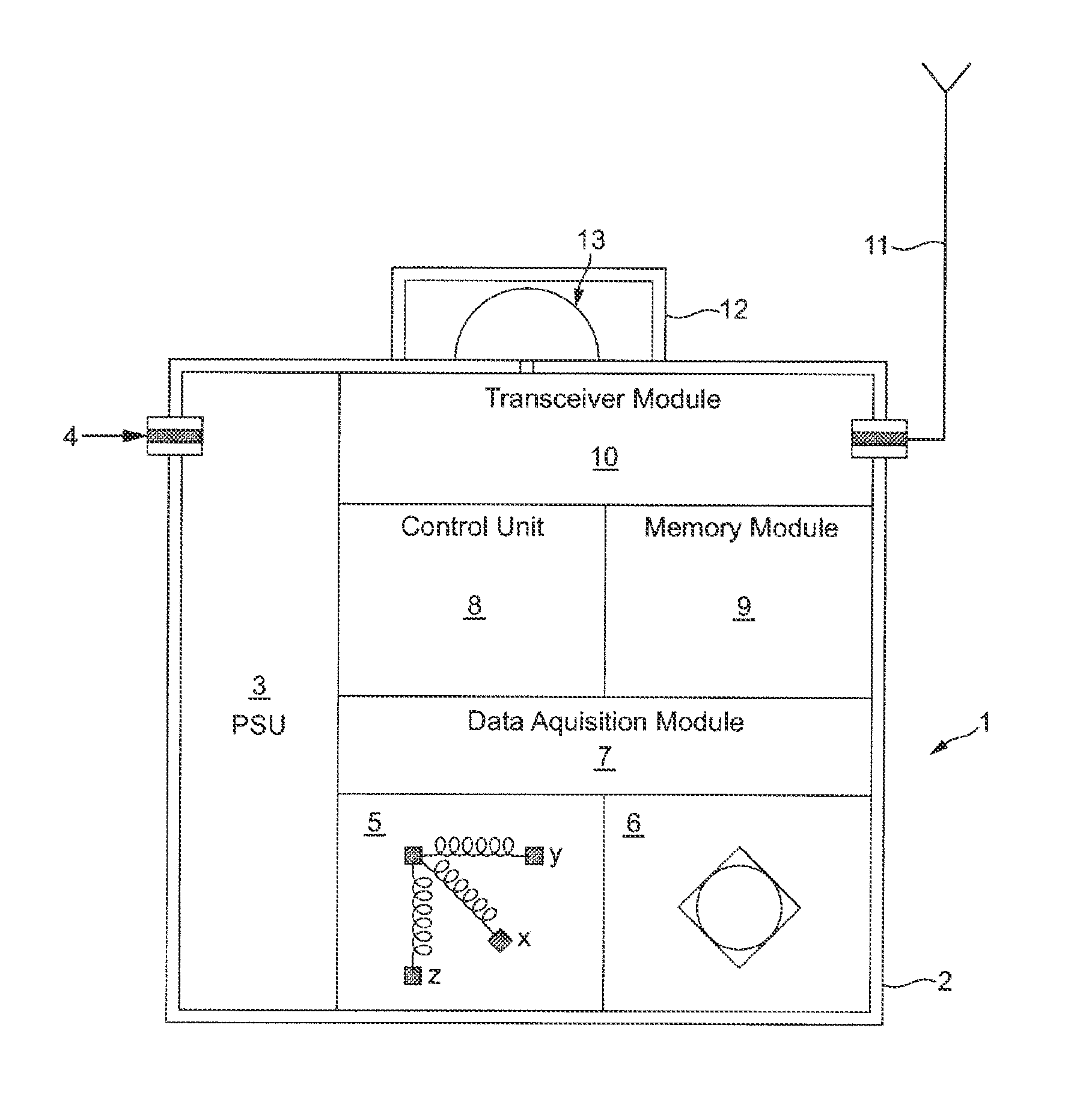
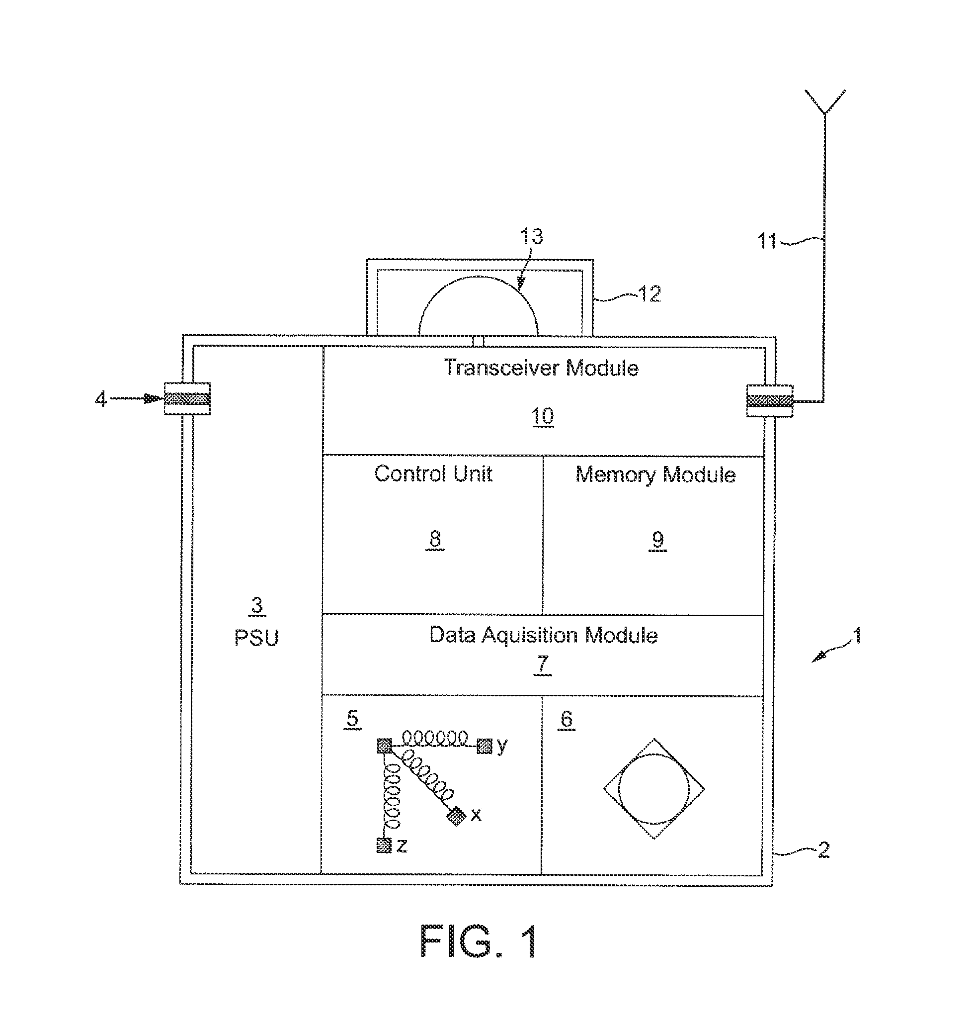
[0017]FIG. 1 is a block diagram of a seismic sensor 1 according to an embodiment of the present invention. The sensor 1 comprises a waterproof and pressure-resistant housing 2 enclosing the sensor's electronic modules. A power supply unit (PSU) 3 is provided with rechargeable batteries to supply power to the modules. The PSU may be connected to an external power supply, which can also be used to recharge the internal batteries, via a connector 4. The sensor includes a 3-component geophone 5 to respond to 3-dimensional physical displacement of the sensor and a hydrophone 6 to respond to water pressure variations. In operation, signals from the geophone 5 and hydrophone 6 are passed to the data acquisition module 7. A control unit 8 manages the data acquisition and storage of the data in a memory module 9. The control unit 8 also manages the receipt and transmission of control signals and data to and from external sources via a transceiver module 10 and an antenna 11. The sensor is pr...


PUM


Abstract

A wireless subsea seismic sensor capable of independent location and operation in arrays, and methods of data collection from arrays of such sensors.

Description

FIELD OF THE INVENTION[0001]Embodiments of the present invention relate to seismic sensors and their method of operation and, in particular, to subsea seismic sensors for subsea deployment in arrays on the sea bed and their operation using wireless communications.BACKGROUND TO THE INVENTION[0002]Seismic surveys are carried out to search for and manage reserves of oil and gas in underground rock formations. Such surveys utilize the reflection or refraction of seismic waves by geologic layers and rock / soil in order to characterize the subsurface geological conditions and structures that may contain hydrocarbons. When rock formations to be surveyed are under the sea, arrays of sensors may be typically deployed on the sea surface, for example, by being towed behind a survey vessel. However, a floating array of sensors can only detect longitudinal or pressure waves (p-waves), because transverse, or shear waves (s-waves) produced from a controlled seismic source of energy do not travel th...

Claims


Application Information

Patent Timeline
Patent Type & Authority Applications(United States)
IPC IPC(8): G01V1/18G01V1/22
CPCG01V1/18G01V1/22G01V1/38G01V1/186G01V1/181H04B11/00
Inventor VANGASSE, ANTHONY JASONPHILLIPS, RAYMONDARNISON, DEAN
Owner GE OIL & GAS UK LTD
Why Eureka
Try Eureka