Hollow structure, and preparation method thereof

a hollow structure and hollow core technology, applied in the direction of structural elements, building components, structural reinforcements, etc., can solve the problems of destroying concrete columns at a strength lower than that expected from a material, requiring a lot of time to construct, and requiring a large and heavy column. to be difficult to treat, so as to reduce the total weight, maximize compressive resistance, and reduce the effect of delivery cos

Active Publication Date: 2015-04-30
AJOU UNIV IND ACADEMIC COOP FOUND
View PDF16 Cites 28 Cited by
  • Summary
  • Abstract
  • Description
  • Claims
  • Application Information

AI Technical Summary

Benefits of technology

[0006]The present invention has been made in an effort to provide a hollow-core structure with an improved structural property and a method of manufacturing the same with which it is easy to handle and manufacture by reducing the total weight due to formation of an inner hollow portion, it is possible to secure safety against buckling and compressive strength by suppressing a premature failure condition, and it is possible to secure economic feasibility by omitting attachment and detachment processes of the formwork.
[0025]According to the hollow-core structure asper the present invention and the manufacturing method thereof, the following effects are expected.
[0026]Firstly, since an inner hollow portion is formed in the structure, the hollow-core structure can be variously applied as in the case where an intermediate structure such as a floor or an inner ladder of a wind-power plant towers is provided. Moreover, it is possible to reduce the total weight, and it is possible to reduce delivery cost.
[0027]Secondly, since the outer peripheral surface of the outer mold is inherently confined by the confinement unit such as a carbon fiber reinforced polymer (CFRP) material, it is possible to maximize compressive resistance, and it is possible to secure safety against a probable local buckling.
[0028]Thirdly, it is possible to apply the hollow-core structure to a precast concrete structure as well as cast-in-place concrete. Compared to the steel structure, the hollow-core structure can be easily manufactured, and can have economical advantages.
[0029]Fourthly, since the inner mold and the outer mold are respectively divided into a plurality of molds to manufacture and the manufactured molds can be detachably coupled to expand, it is possible to manufacture and transfer the hollow-core structure, and it is possible to systemize the hollow-core structure for mass production.

Problems solved by technology

In general, when a concrete column on which a large compressive load and bending act has insufficient lateral confinement or has a tall and narrow shape, such concrete column is destroyed at strength lower than that expected from a material.
According to a traditional design method, in order to avoid such premature failure, it is necessary to unnecessarily increase a cross-section area of the column in a large-scaled structure such as a high-rise building or a high-rise tower, and, thus, a large and heavy column that is difficult to treat may be constructed.
Since a process of providing a formwork, a process of casting concrete, and a process of removing the formwork are performed, it takes a lot of time to construct the concrete column according to the related art and it is also costly to construct the concrete column.
Thus, there is a problem in that it is difficult to reduce construction cost.
However, above-mentioned limitations are not likely to be largely improved due to buckling, and in addition to this, steel structures are vulnerable to corrosion.

Method used


Image

  • Hollow structure, and preparation method thereof
  • Hollow structure, and preparation method thereof
  • Hollow structure, and preparation method thereof

Examples


first embodiment

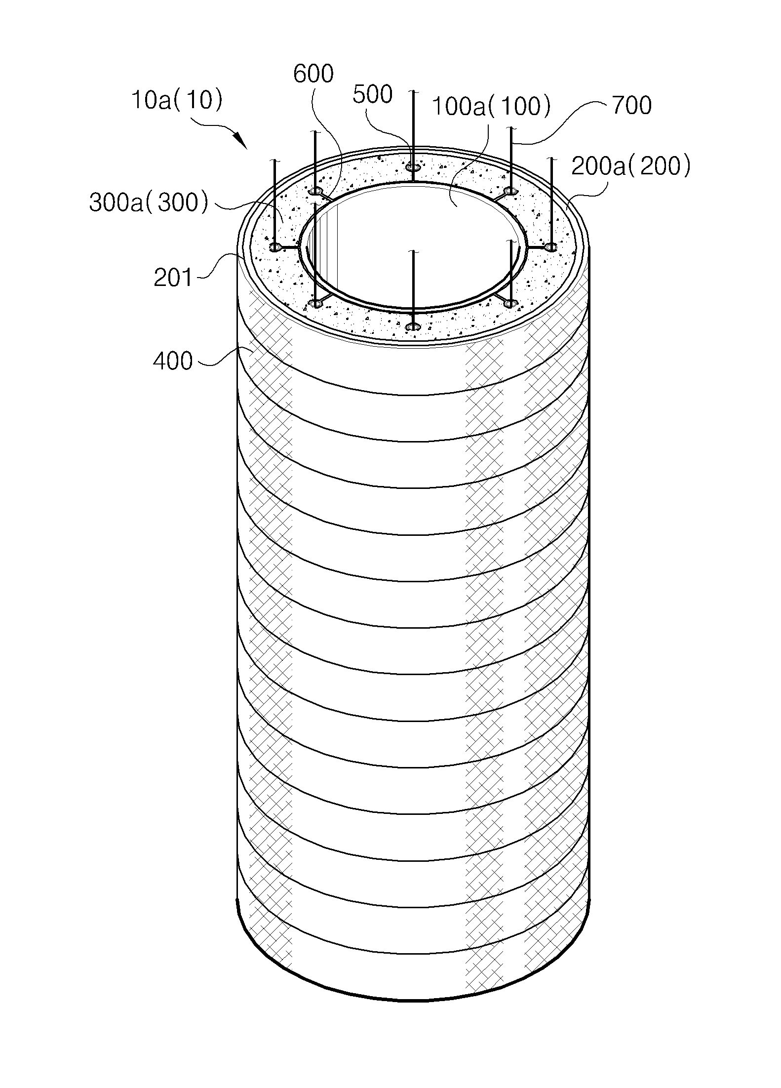
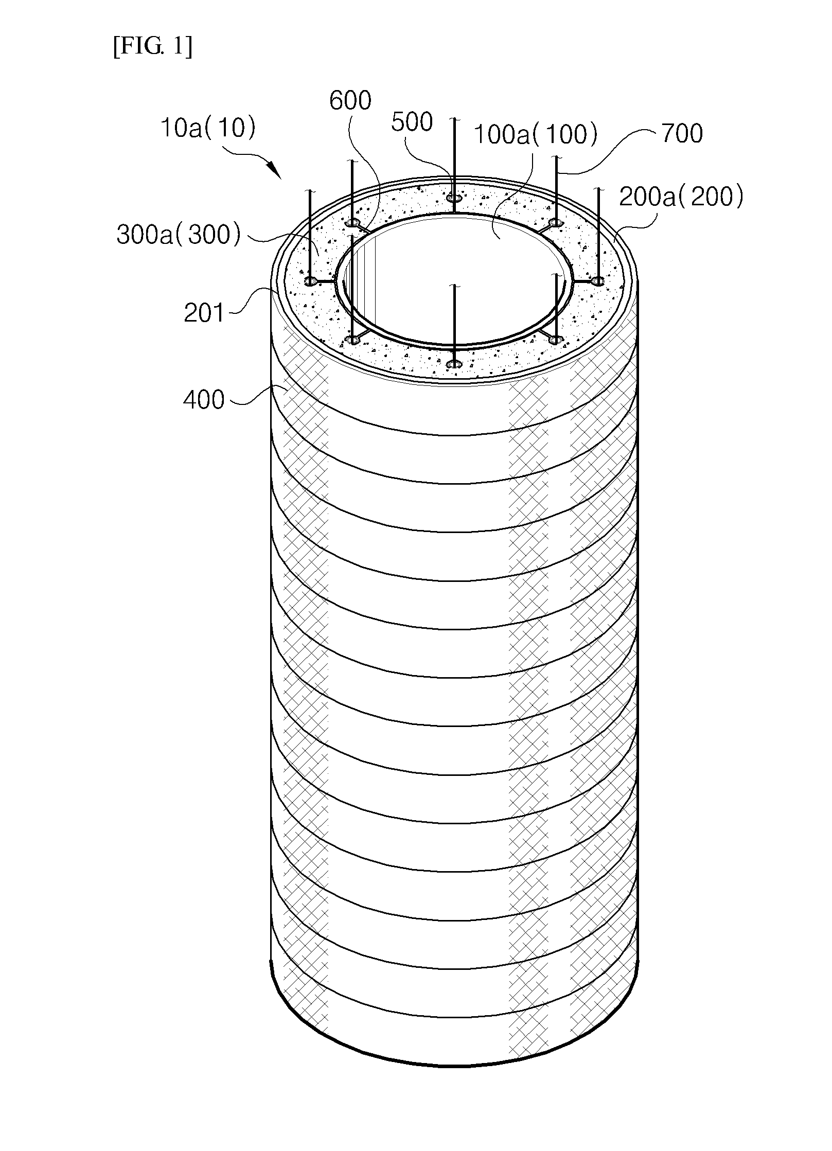
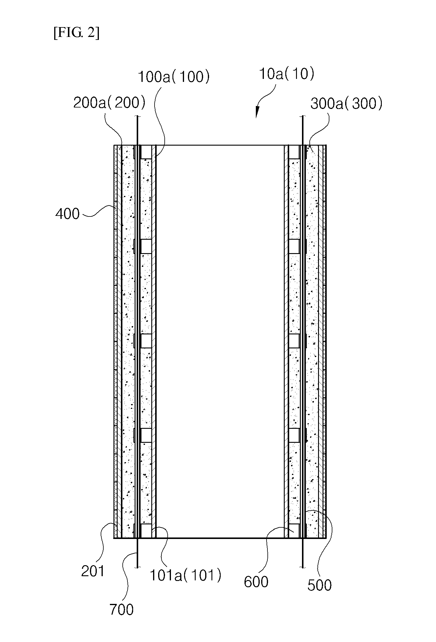
[0049]FIG. 1 is a perspective view illustrating a hollow-core structure asper the present invention, FIG. 2 is a longitudinal cross-sectional view of the hollow-core structure illustrated in FIG. 1, FIG. 3 is a plan cross-sectional view of the hollow-core structure illustrated in FIG. 1, and FIG. 4 is a perspective view illustrating a coupling relationship between an inner mold and a duct illustrated in FIG. 1.

[0050]Referring to the drawings, a hollow-core structure 10a (10) asper a first embodiment of the present invention has an inner hollow portion so as to reduce the total weight, and includes an inner mold 100a (100), an outer mold 200a (200), and a filling member 300a (300).

[0051]The inner mold 100a has a hollow cylindrical shell shape. The inner mold 100a is preferably formed by molding a plastic material. However, any material may be used as long as a material has durability and structural stiffness suitable for purpose, and the material of the inner mold is particularly not...

second embodiment

[0071]Hereinafter, there will be described a hollow-core structure asper the present invention, and the hollow-core structure includes an inner molds and outer molds provided in a plurality of units.

[0072]FIG. 5 is a longitudinal cross-sectional view of the hollow-core structure asper the second embodiment of the present invention, FIG. 6 is a perspective view illustrating an individual inner mold illustrated in FIG. 5, FIG. 7 is a perspective view illustrating another example of the individual inner mold illustrated in FIG. 6, FIG. 8 is a perspective view illustrating a coupling relationship between the inner mold and the duct illustrated in FIG. 5, FIG. 9 is a perspective view illustrating an individual outer mold illustrated in FIG. 5, and FIG. 10 is a perspective view illustrating another example of the individual outer mold illustrated in FIG. 9.

[0073]Here, the same reference numerals as those in FIGS. 1 to 4 represent the same components having the same operations and effects,...

third embodiment

[0092]Hereinafter, a hollow-core structure asper the present invention will be described, and the hollow-core structure includes an inner mold and an outer mold that are respectively formed in a plurality of individual molds.

[0093]FIG. 11 is a longitudinal cross-sectional view of the hollow-core structure asper the third embodiment of the present invention, FIG. 12 is a perspective view of the inner mold illustrated in FIG. 11, FIG. 13 is a perspective view illustrating the outer mold illustrated in FIG. 11, and FIG. 14 is a cross-sectional view illustrating a state where a filling member, the outer mold and the inner mold illustrated in FIG. 11 are coupled.

[0094]Here, the same reference numerals as those in FIGS. 1 to 10 represent the same components having the same operations and effects, and redundant description thereof will not be presented. Differences between the third embodiment and the first embodiment will be mainly described.

[0095]Referring to the drawings, a hollow-core ...


PUM

PropertyMeasurementUnit
structureaaaaaaaaaa
shapeaaaaaaaaaa
shell shapeaaaaaaaaaa

Abstract

A hollow-core structure including: an inner mold that has a hollow cylindrical shell shape; an outer mold that has a hollow cylindrical shell shape to correspond to the inner mold, and in which the inner mold is disposed to be separated; and a filling member that is filled in a separation space between the inner mold and the outer mold.

Description

CROSS REFERENCE TO PRIOR APPLICATIONS[0001]This application is a National Stage Application of PCT International Patent Application No. PCT / KR2012 / 008920 filed on Oct. 29, 2012, under 35 U.S.C. §371, which claims priority to Korean Patent Application No. 10-2012-0056758 filed on May 29, 2012, which are all hereby incorporated by reference in their entirety.BACKGROUND[0002]The present invention relates to a hollow-core structure and a method of manufacturing the same, and more particularly, to a hollow-core structure and a method of manufacturing the same capable of having sufficient structural stiffness and strength while reducing the total weight by forming an inner hollow portion.[0003]In general, when a concrete column on which a large compressive load and bending act has insufficient lateral confinement or has a tall and narrow shape, such concrete column is destroyed at strength lower than that expected from a material. According to a traditional design method, in order to avoi...

Claims


Application Information

Patent Timeline
Patent Type & Authority Applications(United States)
IPC IPC(8): E04C3/34E04C3/36E04C5/08E04B1/22
CPCE04C3/34E04B1/22E04B2103/02E04C5/08E04C3/36B28B21/56B28B21/82E04C5/0604E04C5/07E04C5/208E04B1/18
Inventor KIM, JANG HOON
Owner AJOU UNIV IND ACADEMIC COOP FOUND
Why Eureka
Try Eureka