
Diesel Engine Nox Reduction

a technology for diesel engines and nox reduction, which is applied in the direction of machines/engines, mechanical equipment, and non-fuel substance addition to fuel, etc., can solve the problems of reducing the storage capacity of nosub>x /sub>, putting such responsibility on the end-user to monitor and maintain the scr in working condition, and reducing the nosub>x /sub>. , to achieve the effect of minor fuel penalty

Inactive Publication Date: 2015-04-30
INT ENGINE INTPROP CO LLC
View PDF3 Cites 5 Cited by
  • Summary
  • Abstract
  • Description
  • Claims
  • Application Information

AI Technical Summary

Benefits of technology

The patent describes an engine system that reduces nitrogen oxides in exhaust gas from a diesel engine. The system includes a calibrated engine that reduces nitrogen oxides to low levels. It also includes a lean nitrogen oxide trap that stores and converts nitrates to nitrogen gas during a regeneration event. The system has a primary and secondary exhaust gas recirculation system that circulates and recirculates exhaust gas through the engine. The technical effect of the system is to reduce nitrogen oxides in exhaust gas and improve engine efficiency with a combination of in-cylinder NOx reduction strategies, a lean nitrogen oxide trap, and a secondary exhaust gas recirculation system.

Problems solved by technology

However, the reductants employed by an SCR, such as urea fluid, are typically not naturally found on-board a vehicle.
However, with such systems, it is typically the responsibility of the end-user to maintain a supply of reductant for the supply system.
However, placing such responsibility on the end-user to monitor and maintain the SCR in functioning condition may be problematic.
The LNT catalyst however may become at least partially saturated with NOx over a relatively short time period, which may severely reduce the NOx storage capacity of the LNT catalyst due to a finite amount of NOx storage sites.
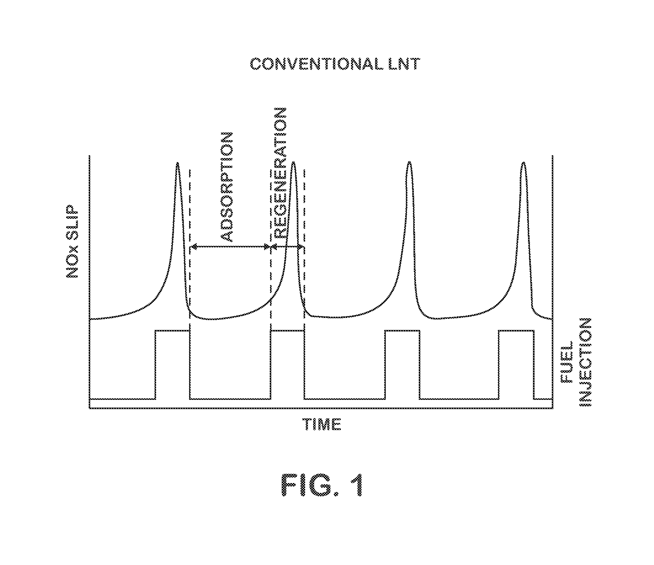
However, as illustrated, frequent regeneration and the associated dosing of exhaust gas with fuel may lead to a relatively high fuel consumption penalty, as well as relatively frequent NOx slip.

Method used


Image

  • Diesel Engine Nox Reduction
  • Diesel Engine Nox Reduction
  • Diesel Engine Nox Reduction

Examples


Embodiment Construction

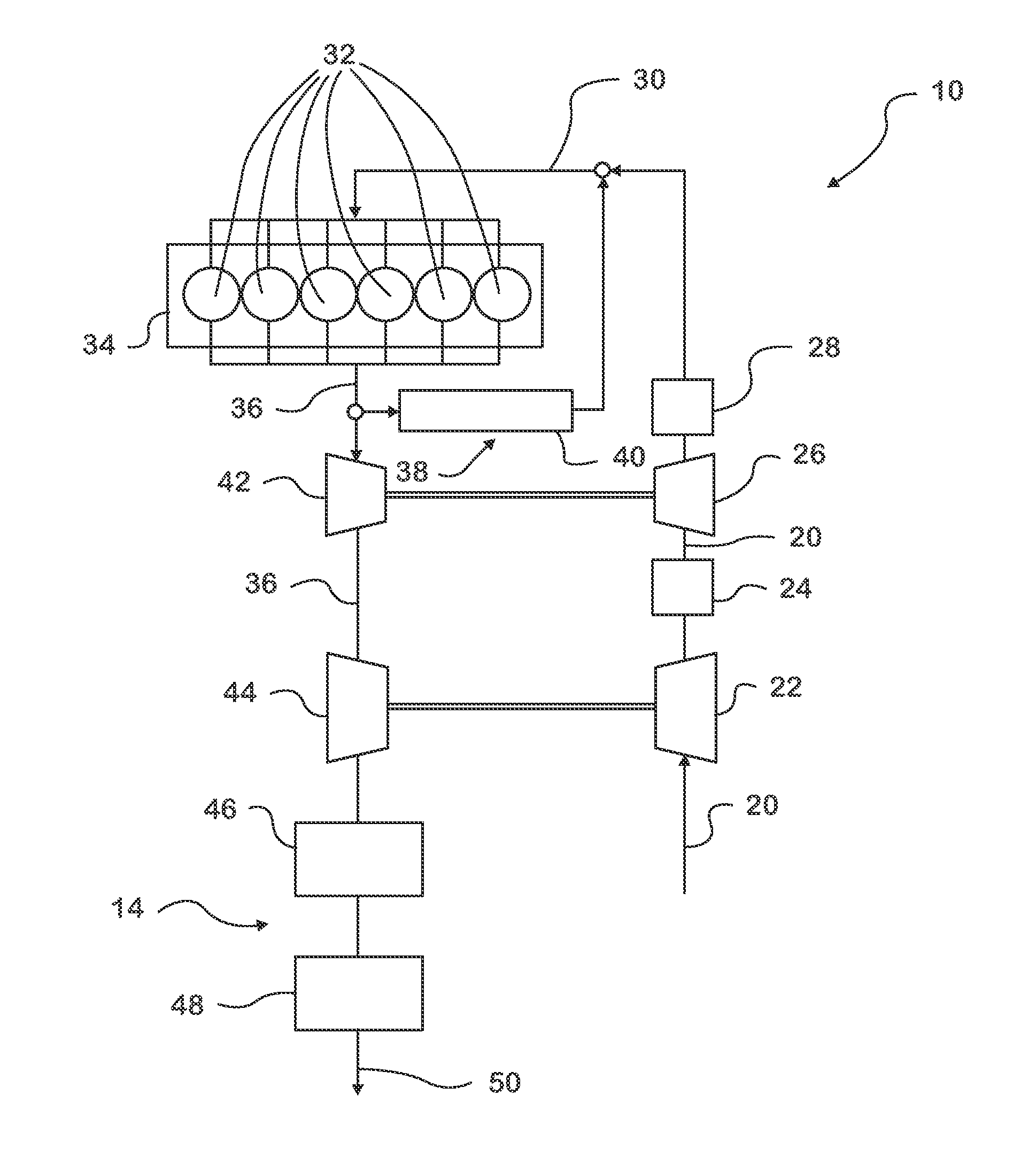
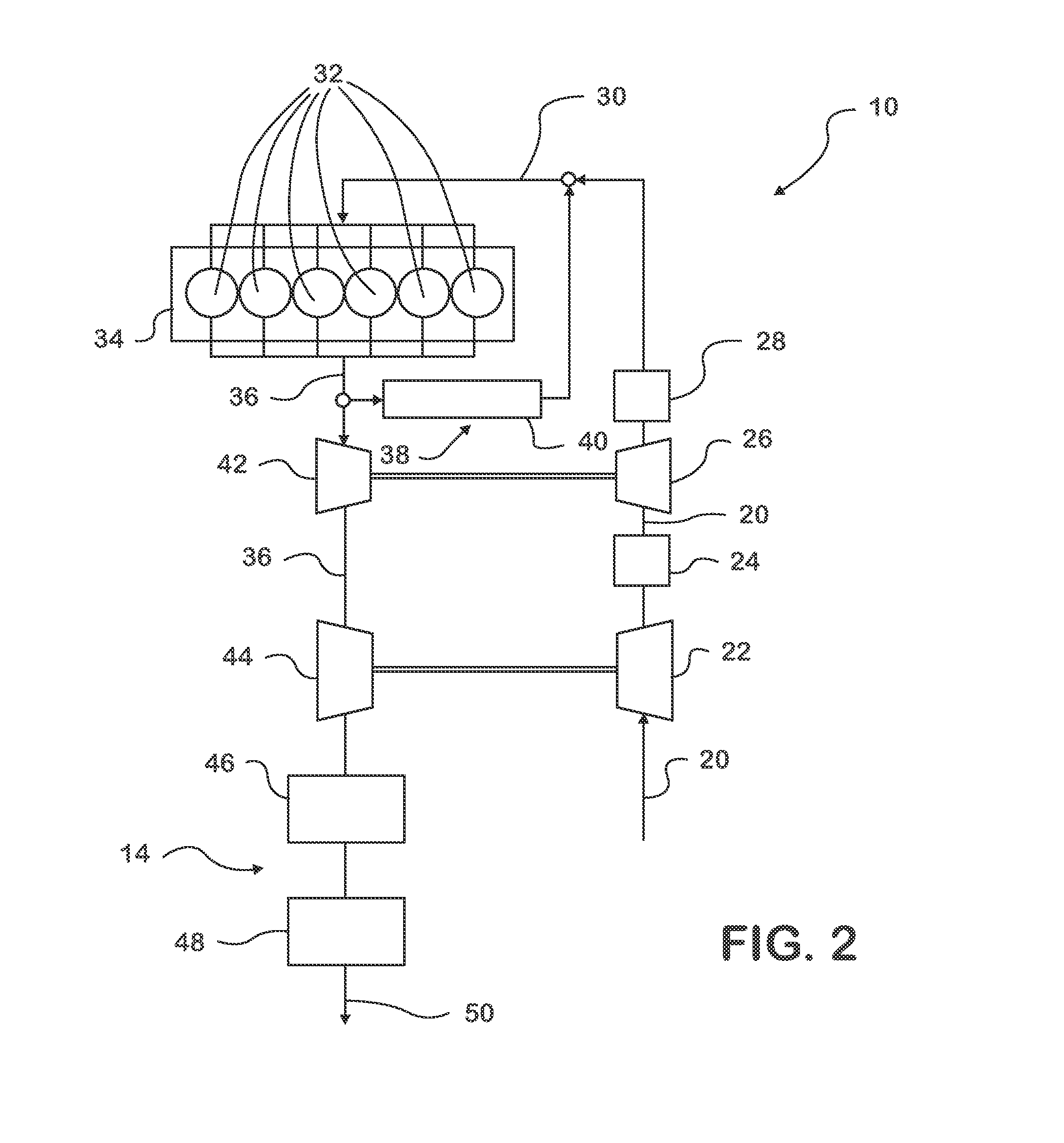
[0015]FIG. 2 illustrates a diesel engine system 10 that includes an exhaust gas after-treatment system 14 having a long-breathing LNT 46. As shown, air for use in the operation of the engine system 10, such as, for example, for use during an internal combustion process, may flow along an intake line 20 that includes various hoses and / or tubes. For example, air passes along a first portion of the intake line 20 and into a low pressure compressor 22 before flowing along a second portion of the intake line 20 to the interstage cooler 24. The air then flows through a high pressure compressor 26 and high pressure charged air cooler 28 before flowing through another portion of the intake line 20 to an intake manifold 30.

[0016]The air may flow through the intake manifold 30 and to cylinders 32 of the engine 34, where the air may be used in a combustion event(s) that is used to displace the pistons of the engine 34, thereby transmitting the force of the combustion event(s) into mechanical p...


PUM


Abstract

An engine system for treating nitrogen oxides present in an exhaust gas generated by the combustion of fuel. The engine system includes one or more long breathing lean nitrogen oxide traps that is / are configured to store at least a portion of the nitrogen oxide in the exhaust gas when the lean nitrogen oxide trap operates in an absorption mode. The lean nitrogen oxide trap is also configured for the conversion of the nitrates stored by the lean nitrogen oxide trap during a regeneration event. The engine-out nitrogen oxide levels may be reduced to extend the duration of the absorption process, thereby reducing both the frequency of regeneration events and the associated fuel penalty. The system may include primary and secondary exhaust gas recirculation systems, with exhaust gas from the secondary system being returned to the engine cylinder to reduce the level of nitrogen oxides in that exhaust gas.

Description

BACKGROUND[0001]Combustion engines may employ emission controls or systems that are configured to reduce the amount of nitrogen oxides (NOx) present in the engine's exhaust gas. One approach to controlling such emissions may include the use of a Selective Catalytic Reduction system (SCR). The SCR typically uses a catalyst and a reductant to convert NOx in the exhaust gas into at least nitrogen gas and water. The reductant may be a liquid or gas, such as, for example, urea, anhydrous ammonia, or aqueous ammonia, among others, that is injected into the stream of exhaust gas generated by the engine.[0002]For example, in instances in which urea is injected into an exhaust gas stream having normal diesel exhaust gas temperatures, the urea undergoes a thermal decomposition and hydrolysis to produce ammonia. The ammonia may then react with NOx on an SCR catalyst substrate to produce nitrogen and water. As the NOx conversion efficiency of SCR catalysts may exceed 80% over a relatively wide ...

Claims


Application Information

Patent Timeline
Patent Type & Authority Applications(United States)
IPC IPC(8): F01N3/08
CPCF01N3/0885F02B37/013F01N13/011F01N3/0814F01N3/0842F01N3/0878F02M26/05F02M26/06F02M26/02F02M26/08F02M26/15Y02T10/12
Inventor DE OJEDA, WILLIAMZHENG, MINGHAN, XIAOYEJEFTIC, MARKOWANG, MEIPING
Owner INT ENGINE INTPROP CO LLC
Learn More