
Nitrogen oxide abatement in semiconductor fabrication

a technology of nitrogen oxide and semiconductors, applied in the direction of separation process, dispersed particle separation, chemistry apparatus and processes, etc., can solve the problems of increasing the flow of processing gases, increasing the nosub>x/sub>emissions from processing, and facilities reaching or exceeding their regulatory limits. , to achieve the effect of reducing nitrogen oxides, reducing nitrogen oxides, and reducing nitrogen oxides

Inactive Publication Date: 2016-09-22
APPLIED MATERIALS INC
View PDF3 Cites 3 Cited by
  • Summary
  • Abstract
  • Description
  • Claims
  • Application Information

AI Technical Summary

Benefits of technology

The patent describes a method and system for reducing nitrogen oxides (NOx) produced by processing systems. The method involves obtaining operating parameters of the processing system and selecting an operating mode for the effluent abatement system based on those parameters. The system includes a controller that can make a determination to abate the effluent by combusting it, exposing it to a plasma, or not, and operate the effluent abatement system accordingly. The technical effect of this patent is to provide a more efficient and effective method for reducing NOx emissions from processing systems.

Problems solved by technology

The increased wafer size leads to increases in the flows of the processing gases required for processing, which in turn leads to increases in the NOx emissions from the processing.
Semiconductor processing facilities have regulatory limits on total NOx emissions, and the increased NOx emissions have the potential to cause the facilities to reach or exceed their regulatory limits.
The process gases used by semiconductor processing facilities include many compounds which must be abated or treated before disposal, due to regulatory requirements and environmental concerns.
However, burning of these materials results in the generation of NOx, due to combustion of the process chemicals and the reaction of nitrogen and oxygen present in the air used in the combustion.

Method used


Image

  • Nitrogen oxide abatement in semiconductor fabrication
  • Nitrogen oxide abatement in semiconductor fabrication
  • Nitrogen oxide abatement in semiconductor fabrication

Examples


Embodiment Construction

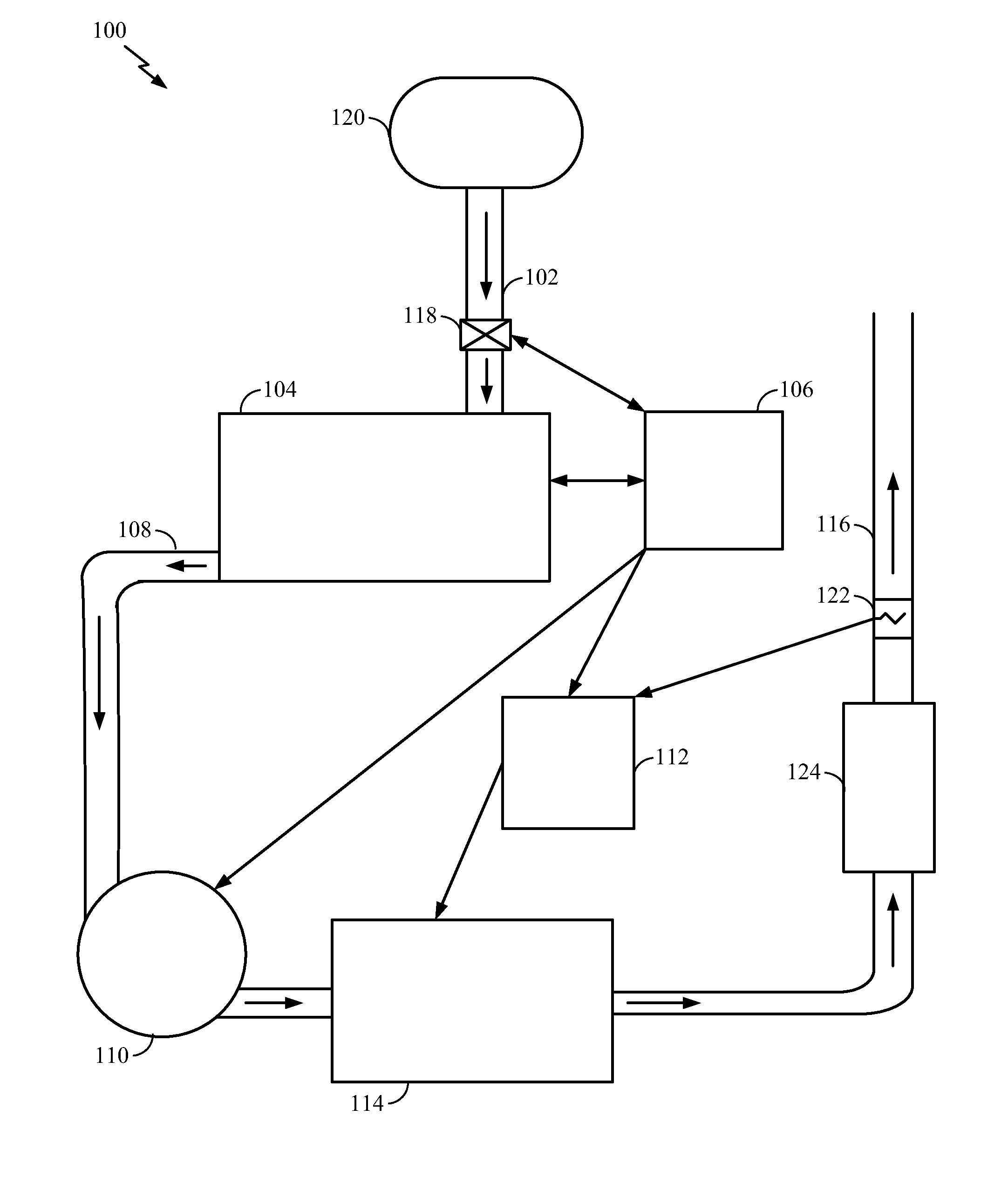
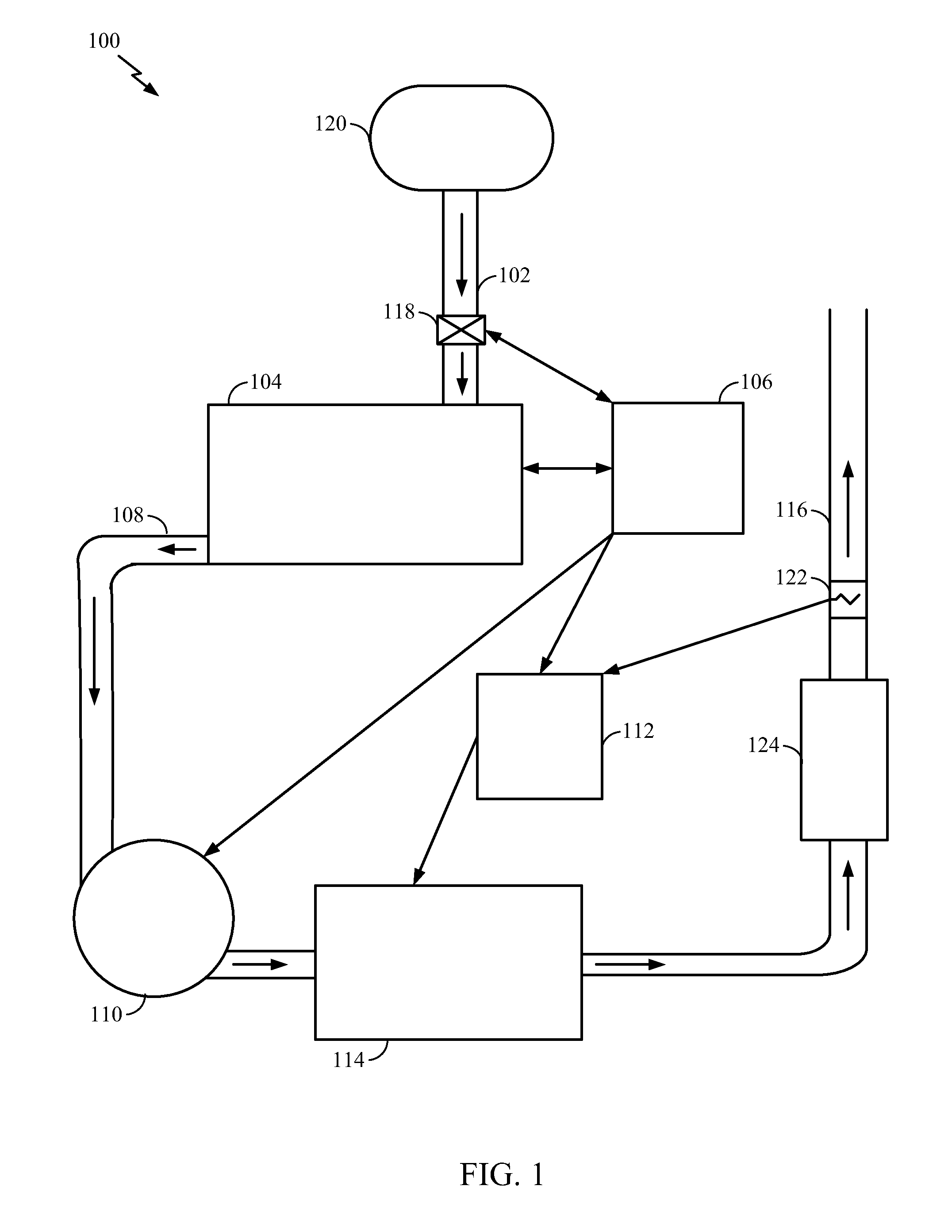
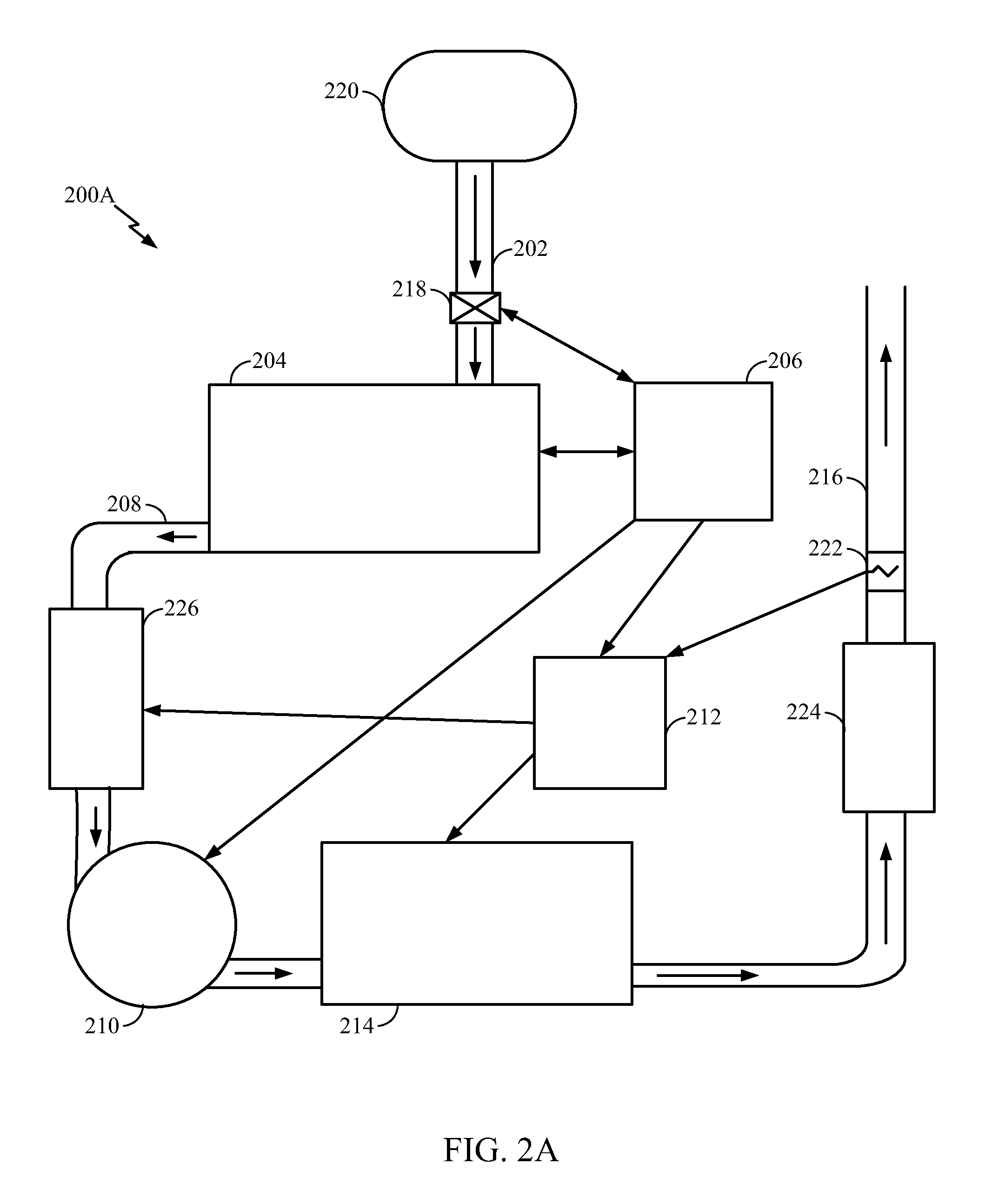
[0017]A control system and methods for reducing NOx production from a processing system are provided. The control system reduces the production of NOx from an effluent abatement system of the processing system. For example, the control system described herein controls a combustion-type effluent abatement system to minimize NOx production in the effluent abatement system while ensuring adequate abatement of chemicals in the effluent. The control system may also control a plasma-type effluent abatement system to minimize NOx production in the effluent abatement system while ensuring adequate abatement of chemicals in the effluent.

[0018]One embodiment disclosed herein selects an operating mode of an effluent abatement system from a group of operating modes, based on at least one operating parameter of a processing system. For example, in one aspect, the effluent abatement system is operated in a first, minimum capacity mode. On initiation of gas flow into the processing system, in resp...


PUM


Abstract

Embodiments enclosed herein relate to methods and apparatus for reducing nitrogen oxides (NOx) produced during processing, such as during semiconductor fabrication processing. A processing system may include an abatement controller and an effluent abatement system, wherein the abatement controller controls the effluent abatement system to reduce NOx production, while ensuring abatement of the effluent gases from the processing system. The effluent abatement system may include a combustion-type effluent abatement system and / or a plasma-type effluent abatement system. The abatement controller may select operating modes of the effluent abatement systems to reduce NOx production.

Description

BACKGROUND OF THE INVENTION[0001]1. Field of the Invention[0002]Embodiments of the present disclosure generally relate to semiconductor processing equipment. More particularly, embodiments of the present disclosure relate to techniques for reducing nitrogen oxides (NOx) produced during semiconductor fabrication.[0003]2. Description of the Related Art[0004]NOx emissions are of increasing importance to the semiconductor processing industry, particularly as fabricators move to processing 450 mm wafers. The increased wafer size leads to increases in the flows of the processing gases required for processing, which in turn leads to increases in the NOx emissions from the processing. Semiconductor processing facilities have regulatory limits on total NOx emissions, and the increased NOx emissions have the potential to cause the facilities to reach or exceed their regulatory limits.[0005]The process gases used by semiconductor processing facilities include many compounds which must be abate...

Claims


Application Information

Patent Timeline
Patent Type & Authority Applications(United States)
IPC IPC(8): H01L21/67B01D53/76B01D53/34B01D53/56
CPCH01L21/67017B01D53/346B01D53/76B01D53/56H01L21/0234H01L21/02343H01L21/67098H01L21/67126H01L21/6715
Inventor FISHER, PAUL E.MCINTOSH, MONIQUEHERBERT, ANDREWDICKINSON, COLIN JOHN
Owner APPLIED MATERIALS INC
Learn More