Spark-ignition direct-injection engine

a direct injection and engine technology, applied in the direction of machines/engines, output power, electric control, etc., can solve the problems of high compression ratio engines, difficult expansion to the high load side, and rapid rise of pressure (dp/dt) with an increase in engine load, etc., to achieve rapid pressure rise and expand the range

Active Publication Date: 2015-04-30
MAZDA MOTOR CORP
View PDF16 Cites 65 Cited by
  • Summary
  • Abstract
  • Description
  • Claims
  • Application Information

AI Technical Summary

Benefits of technology

[0039]In the second specified sub-range of the high load range, in which the engine body is operated by the spark ignition combustion, the fuel injection valve is driven at least at the high fuel pressure of 30 MPa or higher at the timing of injecting the fuel into the cavity formed in the crown surface of the piston. This shortens the fuel injection period, and accelerates the atomization of the fuel spraying. Furthermore, the gas flow in the cavity is strengthened to form the burnable air-fuel mixture in a short time. In addition, the spark ignition starts the combustion while maintaining the great turbulence energy in the cavity, thereby shortening the combustion period. As a result, the abnormal combustion such as the preignition and the knocking effectively reduces, while securing the combustion stability.

Problems solved by technology

An engine with a high compression ratio is subject to knocking, when the operation range is in a low-speed, and high-load range including a full load range.
On the other hand, in a low load operation range, although the compression ignition combustion is possible, preignition combustion occurs, which rapidly raises the pressure (dP / dt) with an increase in the engine load.
Due to noise vibration harshness (NVH) constraints, the range, in which the compression ignition combustion is performed, is difficult to expand to the high load side.

Method used


Image

  • Spark-ignition direct-injection engine
  • Spark-ignition direct-injection engine
  • Spark-ignition direct-injection engine

Examples


Embodiment Construction

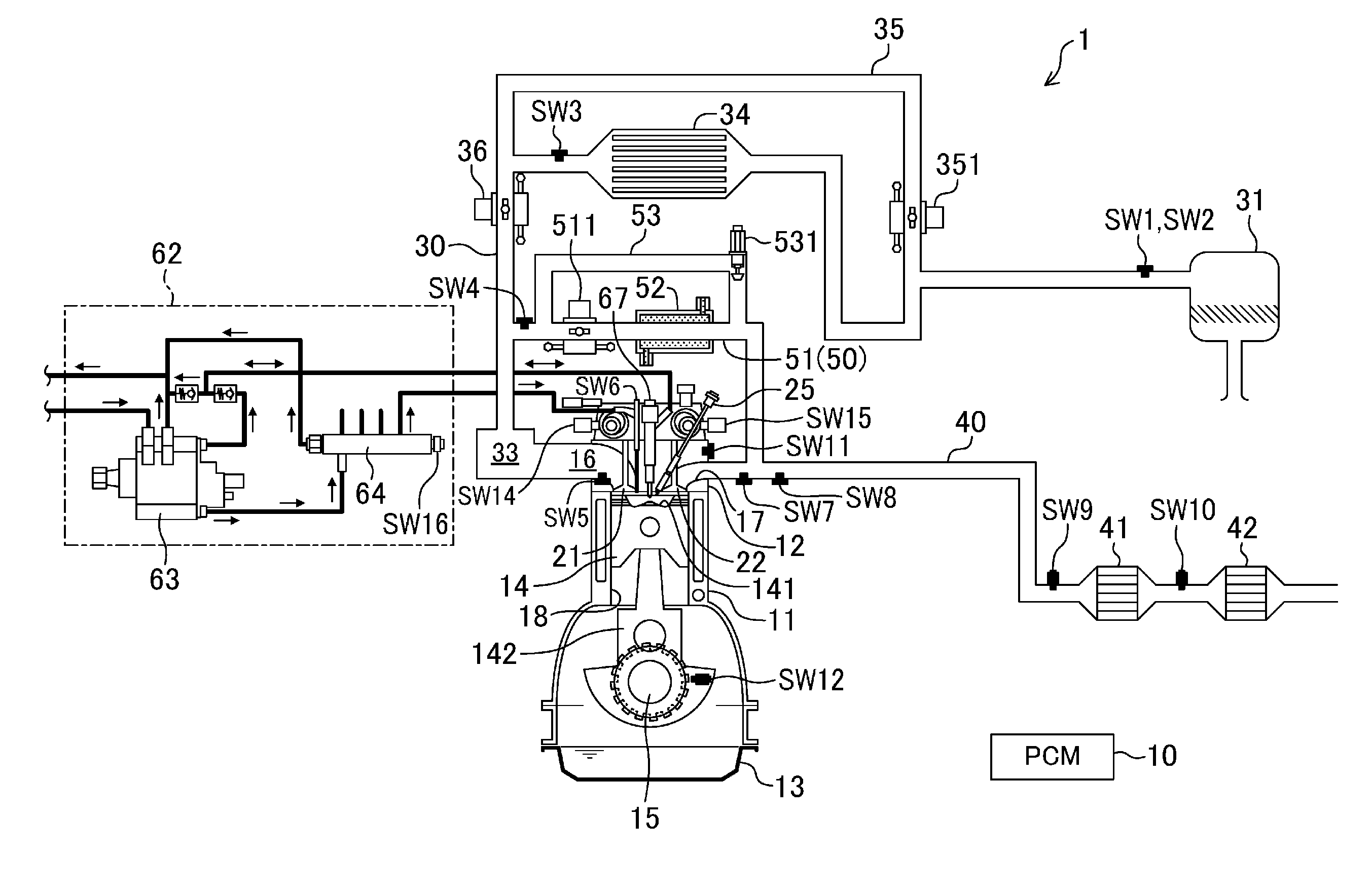
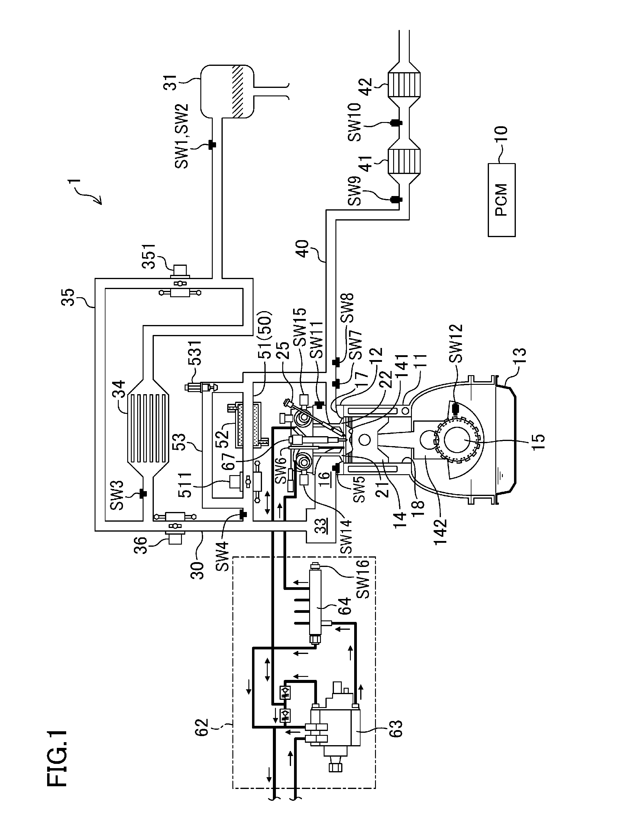
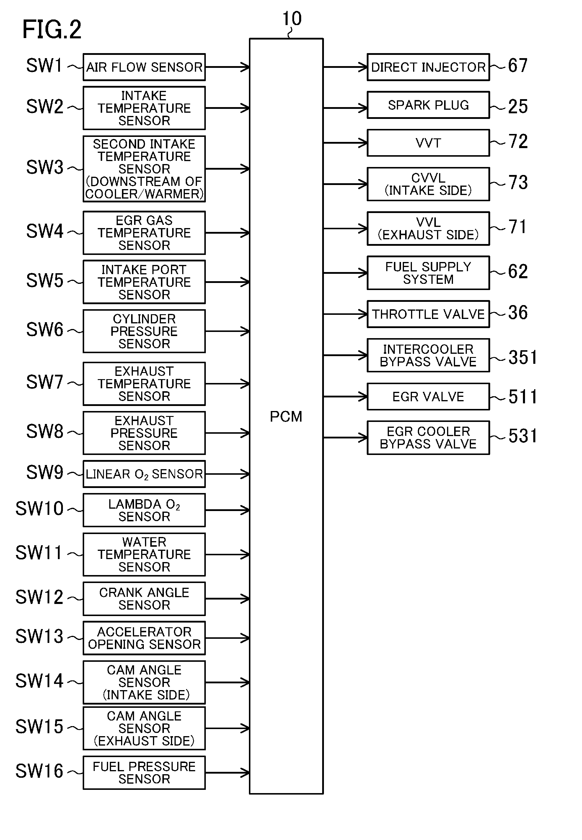
[0091]Embodiments of a spark-ignition direct-injection engine will be described hereinafter with reference to the drawings. The following preferred embodiments are mere examples. FIGS. 1 and 2 illustrate the schematic structure of an engine (i.e., an engine body) 1. The engine 1 is a spark ignition gasoline engine mounted in a vehicle and supplied with fuel containing at least gasoline. The engine 1 includes a cylinder block 11 provided with a plurality of cylinders 18 (although only one is shown in FIG. 1, for example, four cylinders are disposed in series), a cylinder head 12 disposed on the cylinder block 11, and an oil pan 13 disposed under the cylinder block 11 and storing lubricant. A piston 14 is reciprocally fitted in each of the cylinders 18. The piston 14 is connected to a crankshaft 15 via a con rod 142. A cavity 141 like a re-entrant cavity of a diesel engine is formed at the top of the piston 14, as shown in FIG. 3 enlarged. The cavity 141 faces an injector 67, which wi...


PUM


Abstract

A controller injects fuel into a cylinder at a high fuel pressure of 30 MPa or higher, at least in a period between a terminal stage of a compression stroke and an initial stage of an expansion stroke when an operating mode of an engine body is at least in a first specified sub-range of a low load range, and at least in a second specified sub-range of a high load range. The controller sets an EGR ratio in the first specified sub-range to be higher than an EGR ratio in the second specified sub-range, and advances start of fuel injection in the first specified sub-range to start of fuel injection in the second specified sub-range.

Description

TECHNICAL FIELD[0001]The present disclosure relates to spark-ignition direct-injection engines.BACKGROUND ART[0002]In order to improve theoretical thermal efficiency of a spark ignition gasoline engine, increasing the geometrical compression ratio of the engine is effective. For example, Patent Document 1 shows a high compression spark-ignition direct-injection engine with a geometrical compression ratio of 14 or higher. An engine with a high compression ratio is subject to knocking, when the operation range is in a low-speed, and high-load range including a full load range. Patent Document 1 also teaches adjusting the time of closing an intake valve to reduce the effective compression ratio in the low-speed, high-load range. The ignition time is advanced by reducing the knocking as much as possible, thereby increasing the engine torque.[0003]For example, as shown in Patent Document 2, the combustion type of compressing and igniting a lean air-fuel mixture is known as a technique im...

Claims


Application Information

Patent Timeline
Patent Type & Authority Applications(United States)
IPC IPC(8): F02B11/02F02D37/02
CPCF02D37/02F02B11/02F02B23/101F02B29/0418F02D13/0207F02D13/0261F02D21/08F02D41/0057F02D41/3017F02D41/3023F02D41/3035F02D41/401F02D41/402F02D2041/3052F02M26/25F02M26/33F02P5/1516F02P15/08Y02T10/12Y02T10/40
Inventor IWAI, KOUHEIYAMAKAWA, MASAHISANAGATSU, KAZUHIROYOUSO, TAKASHIARAKI, KEIJI
Owner MAZDA MOTOR CORP
Why Eureka
Try Eureka