High-frequency power supply device and ignition voltage selection method

a high-frequency power supply and ignition voltage technology, applied in the direction of electric variable regulation, process and machine control, instruments, etc., can solve the problems of standing wave generation, inability to achieve plasma ignition, and decrease the process reproducibility and reliability of plasma

Active Publication Date: 2015-04-30
KYOSAN ELECTRIC MFG CO LTD
View PDF2 Cites 14 Cited by
  • Summary
  • Abstract
  • Description
  • Claims
  • Application Information

AI Technical Summary

Benefits of technology

[0084]During an RF power supply in which RF power is supplied to a load, the RF power supplying device and the ignition voltage selection method of the present invention can increase the load-end voltage as described above. When the load is a plasma load, an ignition voltage, high enough to generate a plasma discharge, can be selected as the load-end voltage of the plasma load.

Problems solved by technology

Therefore, when a sufficient ignition voltage is not applied, a decrease in the load-end discharge voltage sometimes results in an unstable plasma ignition.
Another known problem is that a standing wave is generated from a forward wave and a reflected wave, which are higher-harmonic components mixed on the transmission line, due to a mismatch among the higher-harmonic components in the RF power.
This standing wave indeterminately varies the generation and the distribution characteristics of plasma and, as a result, decreases process reproducibility and reliability in plasma.

Method used


Image

  • High-frequency power supply device and ignition voltage selection method
  • High-frequency power supply device and ignition voltage selection method
  • High-frequency power supply device and ignition voltage selection method

Examples


Embodiment Construction

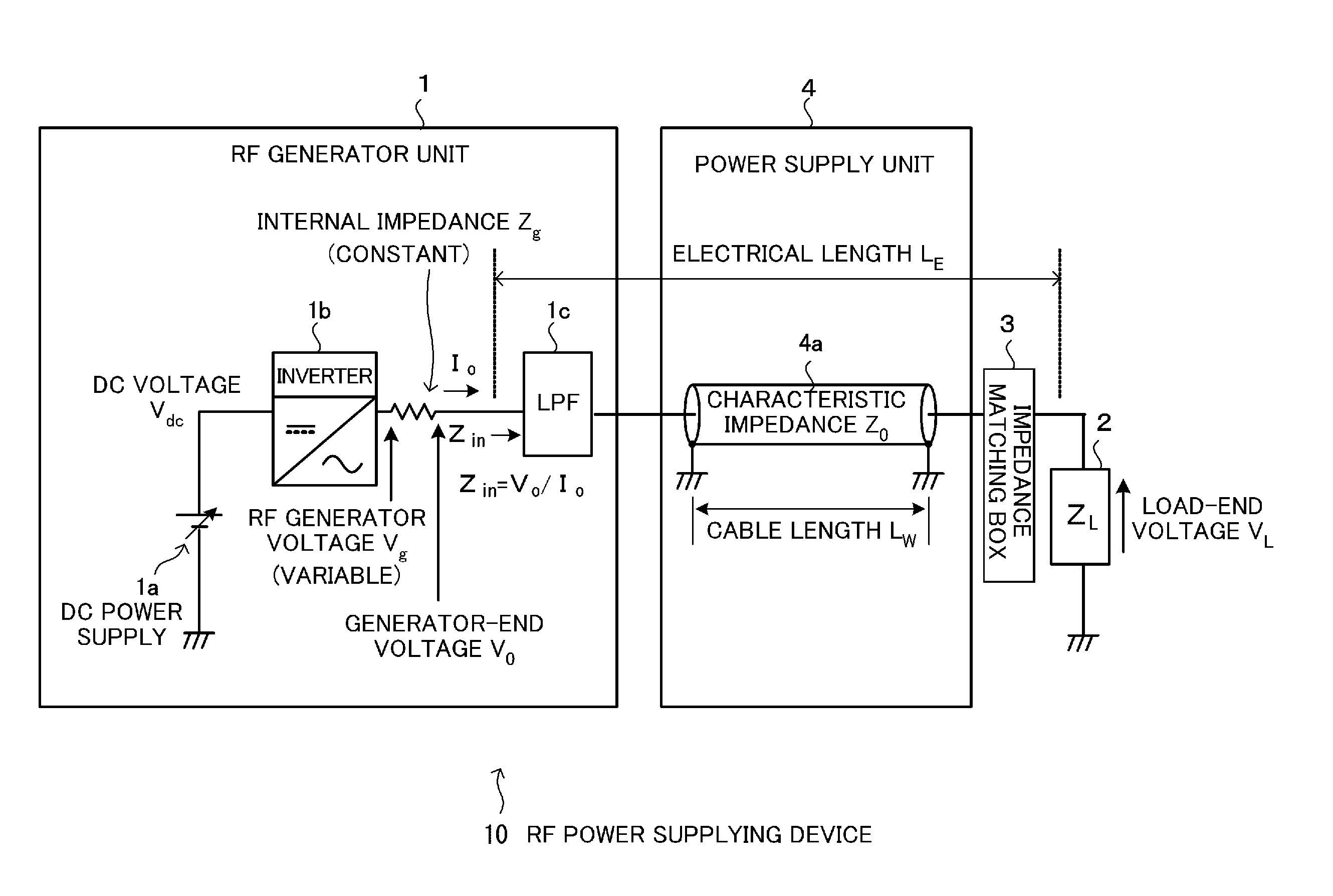
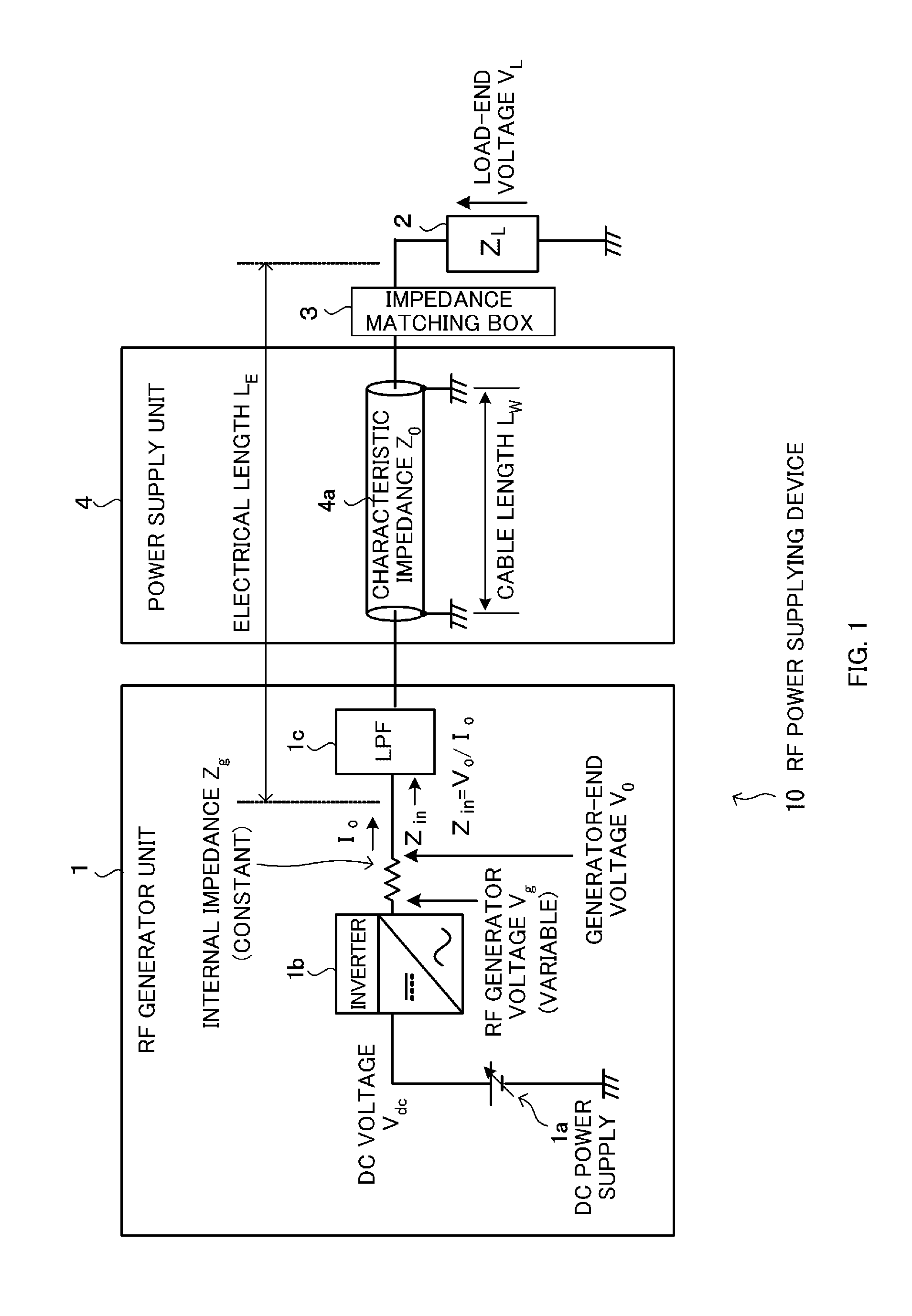
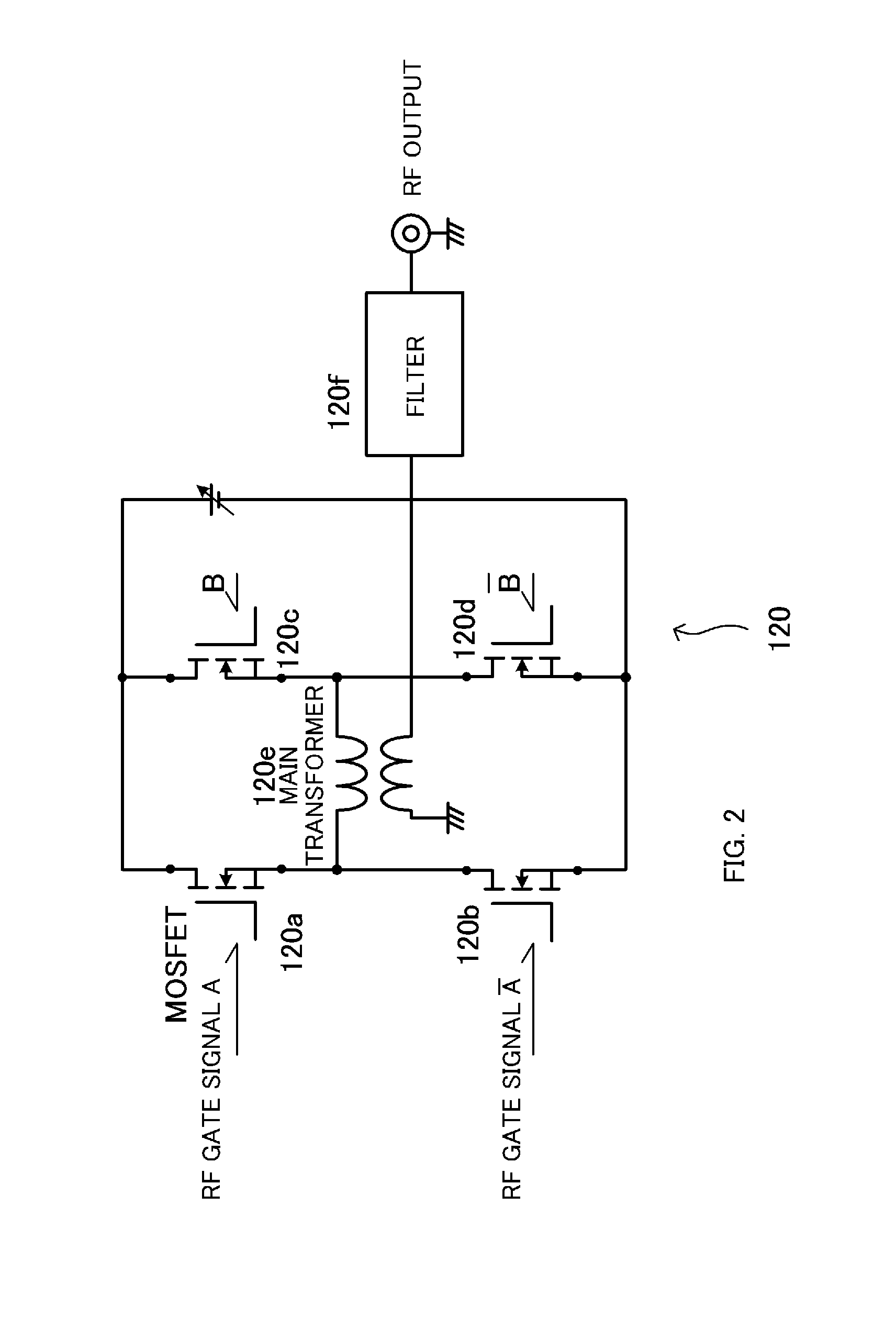
[0098]Embodiments of the present invention are described below in detail with reference to the drawings. The following describes an RF power supplying device and an ignition voltage selection method of the present invention. An example of the configuration of an RF power supplying device is described with reference to FIG. 1, an example of one configuration of an RF power amplifier circuit provided in an RF generator device of the present invention is described with reference to FIG. 2, the signals of the RF power amplifier circuit are described with reference to FIG. 3, the relation between the electrical length of a power supply unit and the load-end voltage is described with reference to FIG. 4, an example of the selection of the electrical length of the power supply unit of the present invention is described with reference to FIG. 5, the relation between the electrical length LE and the load-end voltage (Vz(z=LE)) is described with reference to FIG. 6, the relation between the e...


PUM


Abstract

When RF power is supplied from an RF generator to a load via a power supply unit,
  • (a) the internal impedance of the RF generator is made lower than the characteristic impedance of the power supply unit, and
  • (b) the load-end voltage is increased by selecting the electrical length LE of the power supply unit, which connects between the RF generator and the load to supply RF power, so that the electrical length LE has a predetermined relation with the fundamental wavelength λ of the RF AC. More specifically, the electrical length LE of the power supply unit is selected in such a way that, when the load end, which is the input end of the load, is in an open state, the electrical length LE is (2n−1)·(λ/4)−k·λ≦LE≦(2n−1)·(λ/4)+k·λ (n is an integer, k is {π−2·cos−1(1/K)}/(4π)) with respect to the fundamental wavelength λ of the RF AC.

Description

TECHNICAL FIELD[0001]The present invention relates to an RF generator device, which supplies RF power to a load, and to the selection of a voltage that the RF generator device outputs for generating a predetermined load-end voltage at a load end (an input end on the load side) when RF power is supplied from the RF generator device to the load. More particularly, when the load is a plasma load, the present invention relates to the voltage selection of an ignition voltage (firing voltage) that is a firing voltage when RF power is supplied to the plasma load to generate a plasma discharge.BACKGROUND ART[0002]A plasma treatment device is a device that generates a plasma discharge by supplying RF power to the electrodes, arranged in a reactor in which plasma is generated, and performs surface treatment for a substrate using the generated plasma. The plasma treatment device is used for semiconductor fabrication and so on.[0003]FIGS. 11 and 12 are diagrams showing an example of the configu...

Claims


Application Information

Patent Timeline
Patent Type & Authority Applications(United States)
IPC IPC(8): H05H1/46H02M7/5387
CPCH01J37/32174H05H2001/4682H02M7/53871H05H1/46H02M7/5387H01J37/32091H01J37/32183H05H2242/26
Inventor YUZURIHARA, ITSUOAIKAWA, SATOSHIKUNITAMA, HIROSHI
Owner KYOSAN ELECTRIC MFG CO LTD
Why Eureka
Try Eureka