Oscillation circuit, oscillator, manufacturing method of oscillator, electronic device, and moving object
- Summary
- Abstract
- Description
- Claims
- Application Information
AI Technical Summary
Benefits of technology
Problems solved by technology
Method used
Image

Examples
first embodiment
1. Oscillation Circuit
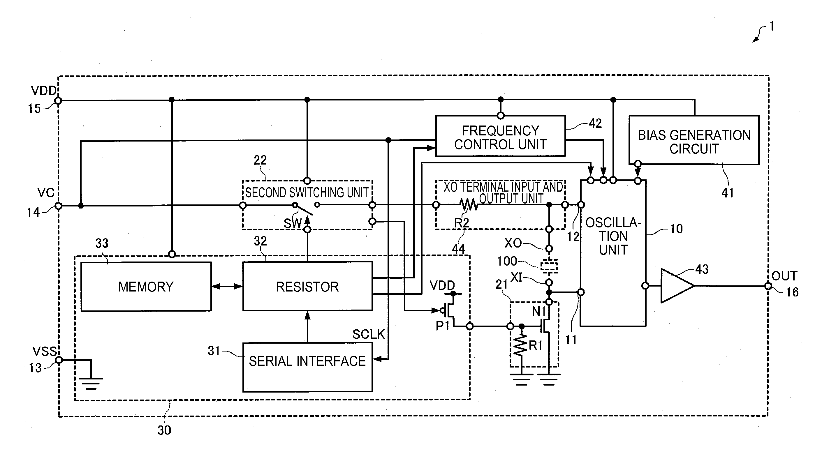
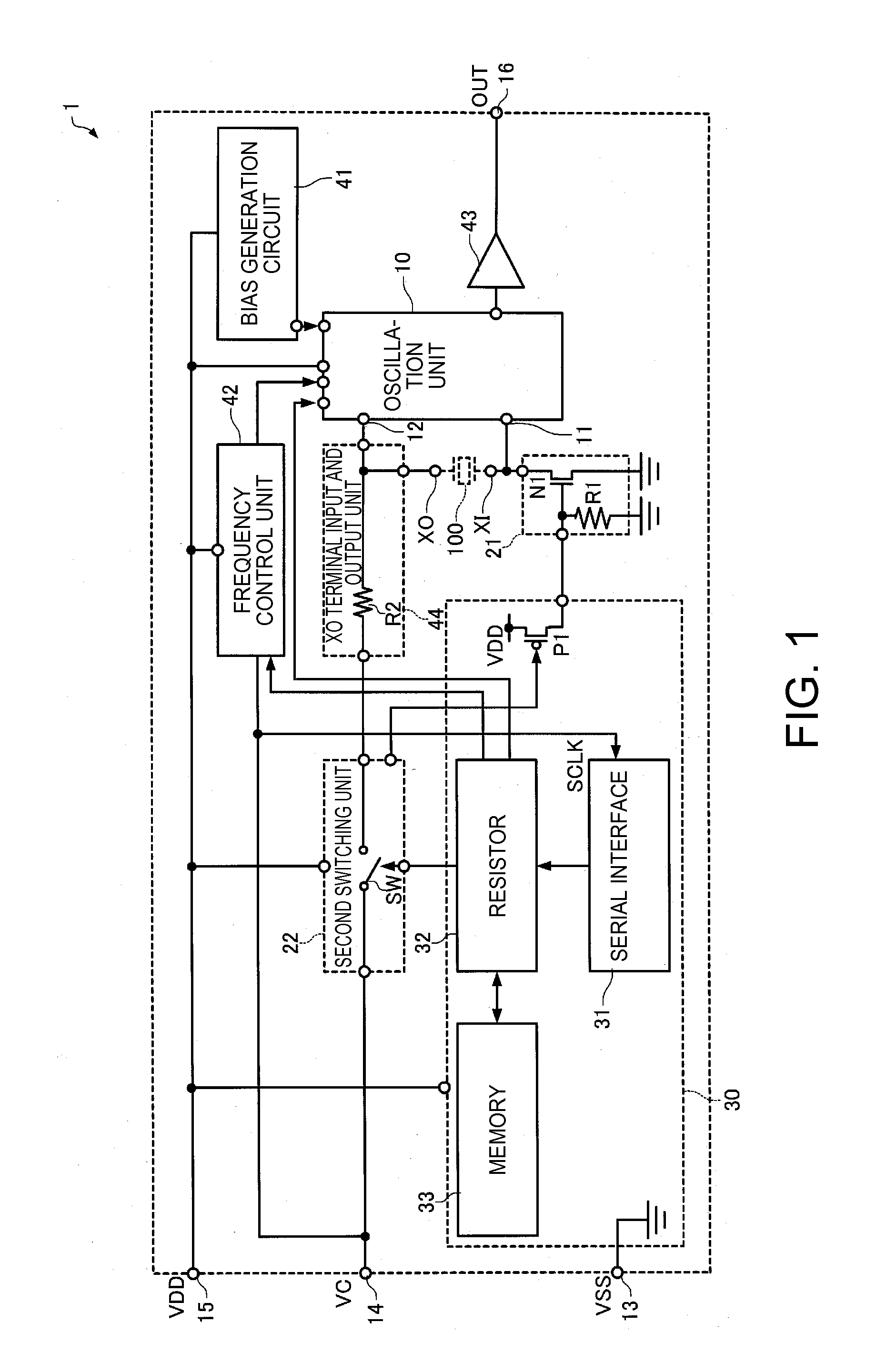
[0059]FIG. 1 is a circuit diagram of an oscillation circuit 1 according to a first embodiment. A part or an entirety of the oscillation circuit 1 may be configured with a semiconductor device.
[0060]The oscillation circuit 1 according to the embodiment includes an oscillation section which uses a vibrator 100 as a frequency source and includes a feedback conduction path between the vibrator 100 and the oscillation section, a path through which a signal passes from the oscillation section to the vibrator 100, a path through which a signal passes from the vibrator 100 to the oscillation section, and an impedance control section which controls an impedance between the path through which a signal passes from the vibrator 100 to the oscillation section and a ground conduction path. The oscillation circuit 1 according to the first embodiment as an example of the invention has a configuration of not including the vibrator 100, but the vibrator 100 may be included in th...
second embodiment
2. Oscillation Circuit
[0106]FIG. 7 is a circuit diagram of an oscillation circuit 1a according to a second embodiment. The same reference numerals are used for the same configuration as in the oscillation circuit 1 shown in FIG. 1, and specific description thereof will be omitted.
[0107]In the oscillation circuit 1a according to the embodiment, a terminal which also functions as a terminal to which an output signal of the output buffer 43 is output is set as the fourth terminal 14, and a terminal which also functions as a terminal for frequency control is set as the sixth terminal 16. The oscillation circuit 1a includes a second switching unit 22a, and the second switching unit 22a switches modes of electrical connection between the second terminal 12 and the fourth terminal 14.
[0108]Since the fourth terminal 14 of the oscillation circuit 1a is normally not a terminal to which a signal is normally input by a user, as the second switching unit 22a, a simple analog switch without an in...
third embodiment
3. Oscillation Circuit
[0109]FIG. 8 is a circuit diagram of an oscillation circuit 1b according to a third embodiment. The same reference numerals are used for the same configuration as in the oscillation circuit 1 shown in FIG. 1, and specific description thereof will be omitted.
[0110]The oscillation circuit 1b according to the embodiment includes a seventh terminal 17 as a terminal for frequency control, and the fourth terminal 14 and the seventh terminal 17 are configured as independent terminals.
[0111]Even with the oscillation circuit 1b, the same effects as those of the oscillation circuit 1 are obtained for the same reasons. In addition, since the fourth terminal 14 and the seventh terminal 17 are configured to be independent, it is possible to omit the second switching unit 22. Accordingly, it is possible to reduce a circuit size.
4. Oscillator
[0112]FIG. 9 is a cross-sectional view of an oscillator 1000 of the embodiment. The oscillator 1000 includes an electronic component 2 a...
PUM
 Abstract
Description
Claims
Application Information
 - R&D
- Intellectual Property
- Life Sciences
- Materials
- Tech Scout
- Unparalleled Data Quality
- Higher Quality Content
- 60% Fewer Hallucinations
Browse by: Latest US Patents, China's latest patents, Technical Efficacy Thesaurus, Application Domain, Technology Topic, Popular Technical Reports.
© 2025 PatSnap. All rights reserved.Legal|Privacy policy|Modern Slavery Act Transparency Statement|Sitemap|About US| Contact US: help@patsnap.com