

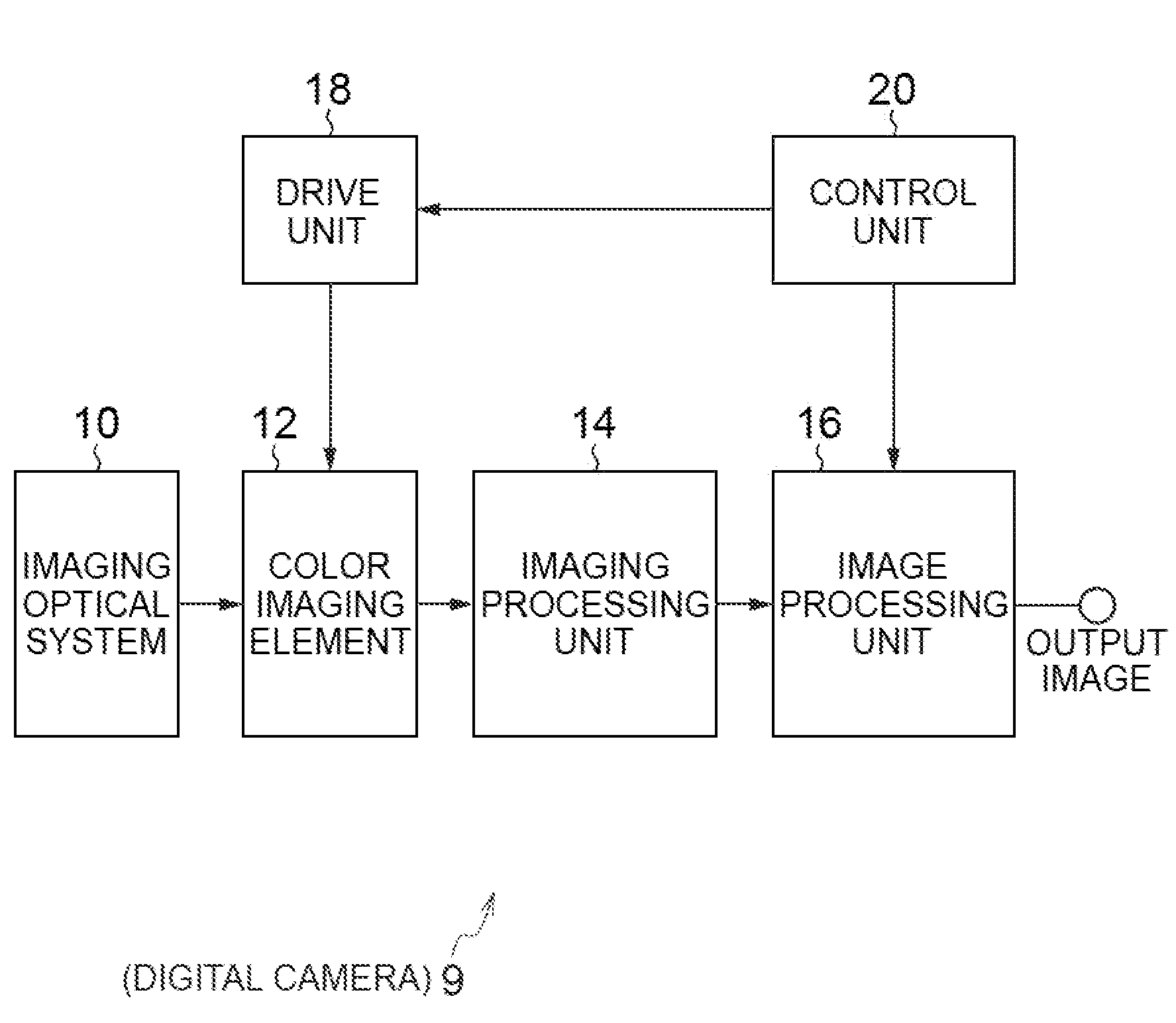
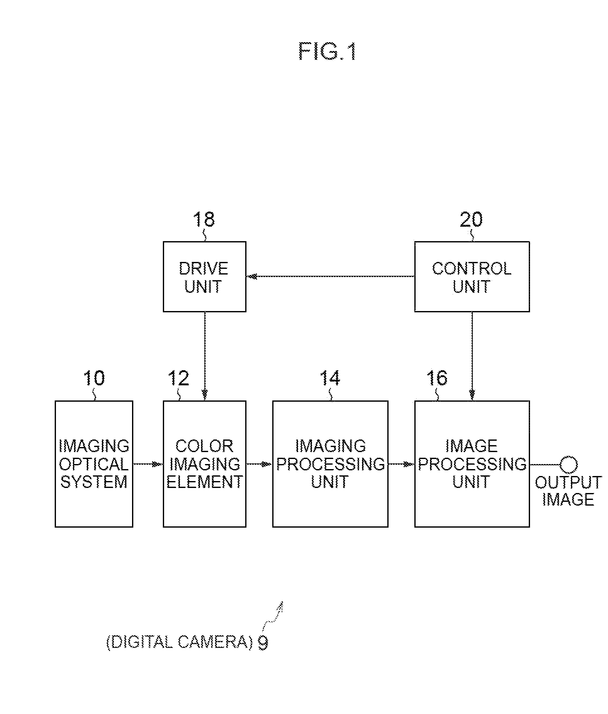
Color imaging element and imaging device
a color imaging element and imaging device technology, applied in the direction of solid-state device signal generators, picture signal generators, television systems, etc., can solve the problems of general color filters that do not address image quality defects, complex de-mosaic processing, and no idea in general color filters, etc., to reduce the occurrence of false colors, improve the effect of color accuracy and high precision
- Summary
- Abstract
- Description
- Claims
- Application Information
AI Technical Summary
Benefits of technology
Problems solved by technology
Method used
Image

Examples
first embodiment
[0078]A color filter array 22 according to the present embodiment has the following characteristics.
[Characteristics (1)]
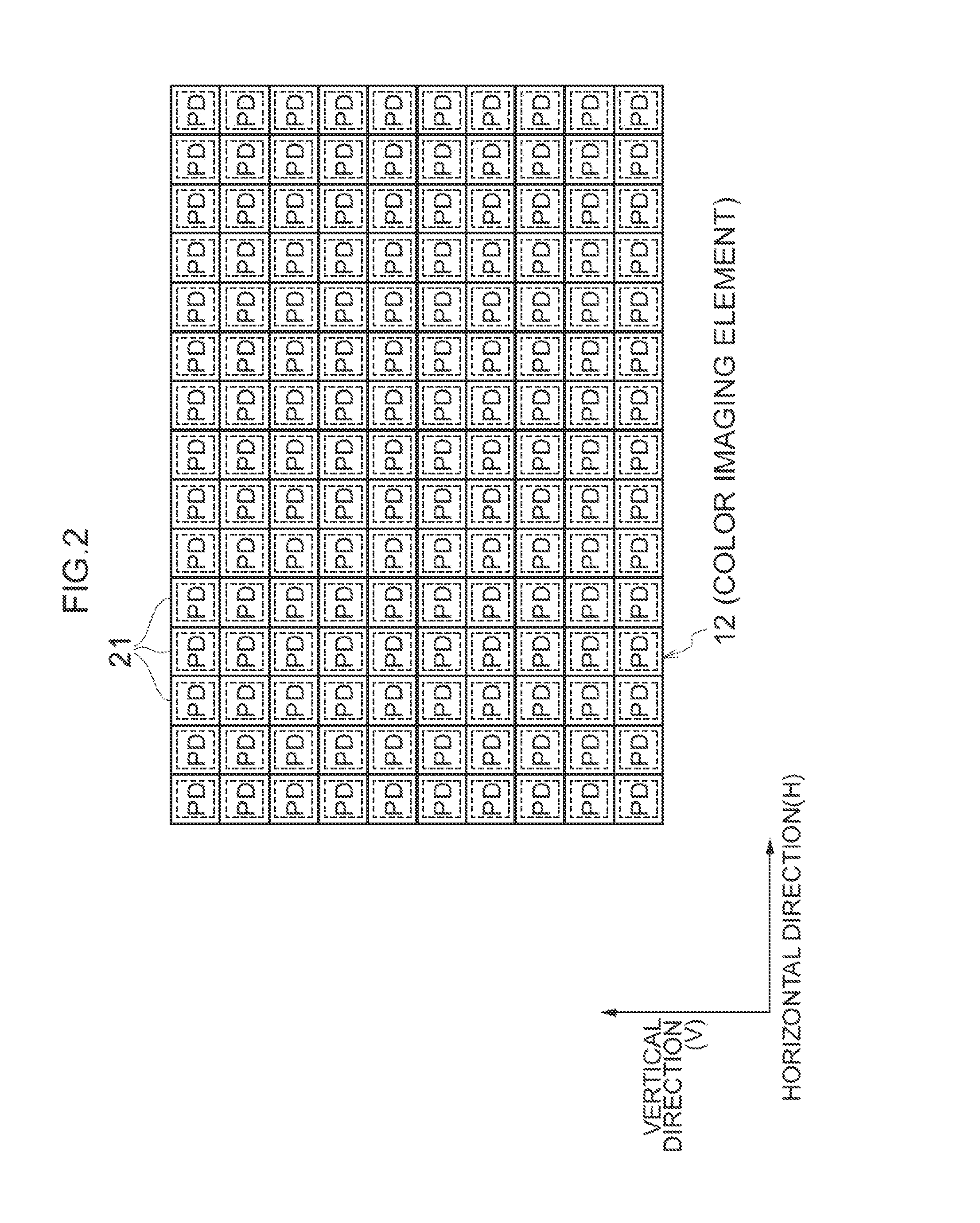
[0079]As shown in (a), (b) portions of FIG. 3, the color filter array 22 includes a basic array pattern P1 which is a square array pattern corresponding to 4×4 pixels (M×N pixels) in the horizontal direction and in the vertical direction, and this basic array pattern P1 is repeatedly disposed in the horizontal direction and in the vertical direction. This basic array pattern P1 includes R filters 23R, G filters 23G, B filters 23B and transparent filters 23W of each color. Therefore, in the color filter array 22, the R filters 23R, the G filters 23G, the B filters 23B and the transparent filters 23W are periodically arranged.
[0080]Therefore, when de-mosaic processing, or the like, is performed on the R, G, B signals retrieved from the color imaging element 12, the processing can be performed according to the repeating pattern. As a result, it is possible to simplif...
second embodiment
[0105]FIG. 4 is a diagram showing a basic array pattern of color filters according to the second embodiment, and (a) portion shows one basic array pattern P2, and (b) portion shows a state where total of nine basic array patterns P2 are disposed, three in the horizontal direction and three in the vertical direction.
[0106]In the present embodiment, the explanation of the features which are the same as or similar to those in the above-described first embodiment will be omitted.
[0107]The array of color filters of the present embodiment is an array in which R filters 23R and B filters 23B in the color filters according to the first embodiment shown in FIG. 1 are inverted. That is, the positions of the R filters 23R in the color filter array according to the first embodiment correspond to the positions of the B filters 23B in the color filter array according to the second embodiment, and the positions of the B filters 23B in the color filter array according to the first embodiment corres...
third embodiment
[0121]FIG. 5 is a diagram showing a basic array pattern of color filters according to the third embodiment, and (a) portion shows one basic array pattern P3, and (b) portion shows a state where total of nine basic array patterns P2 are disposed, three in the horizontal direction and three in the vertical direction.
[0122]In the present embodiment, the explanation of the features which are the same as or similar to those in the above-described first embodiment will be omitted.
[0123]In the basic array pattern P3 of the present embodiment, four types of pixel lines (a first filter horizontal array 25a, a second filter horizontal array 25b, a third filter horizontal array 25c and a fourth filter horizontal array 25d) extending in parallel in the horizontal direction are sequentially arranged in the vertical direction (see (a) portion of FIG. 5). The first filter horizontal array 25a is a “filter array in which a transparent filter 23W, a B filter 23B, a transparent filter 23W and a G fil...
PUM
 Abstract
Description
Claims
Application Information