
Backlight module and liquid crystal display device using same

a backlight module and liquid crystal display technology, applied in mechanical equipment, lighting and heating equipment, instruments, etc., can solve the problems of deterioration of the strength of the pcb and achieve the effect of improving the quality of the liquid crystal display device, simple structure, and ensuring the mounting strength of the printed circuit board

Active Publication Date: 2015-04-30
TCL CHINA STAR OPTOELECTRONICS TECH CO LTD
View PDF2 Cites 7 Cited by
  • Summary
  • Abstract
  • Description
  • Claims
  • Application Information

AI Technical Summary

Benefits of technology

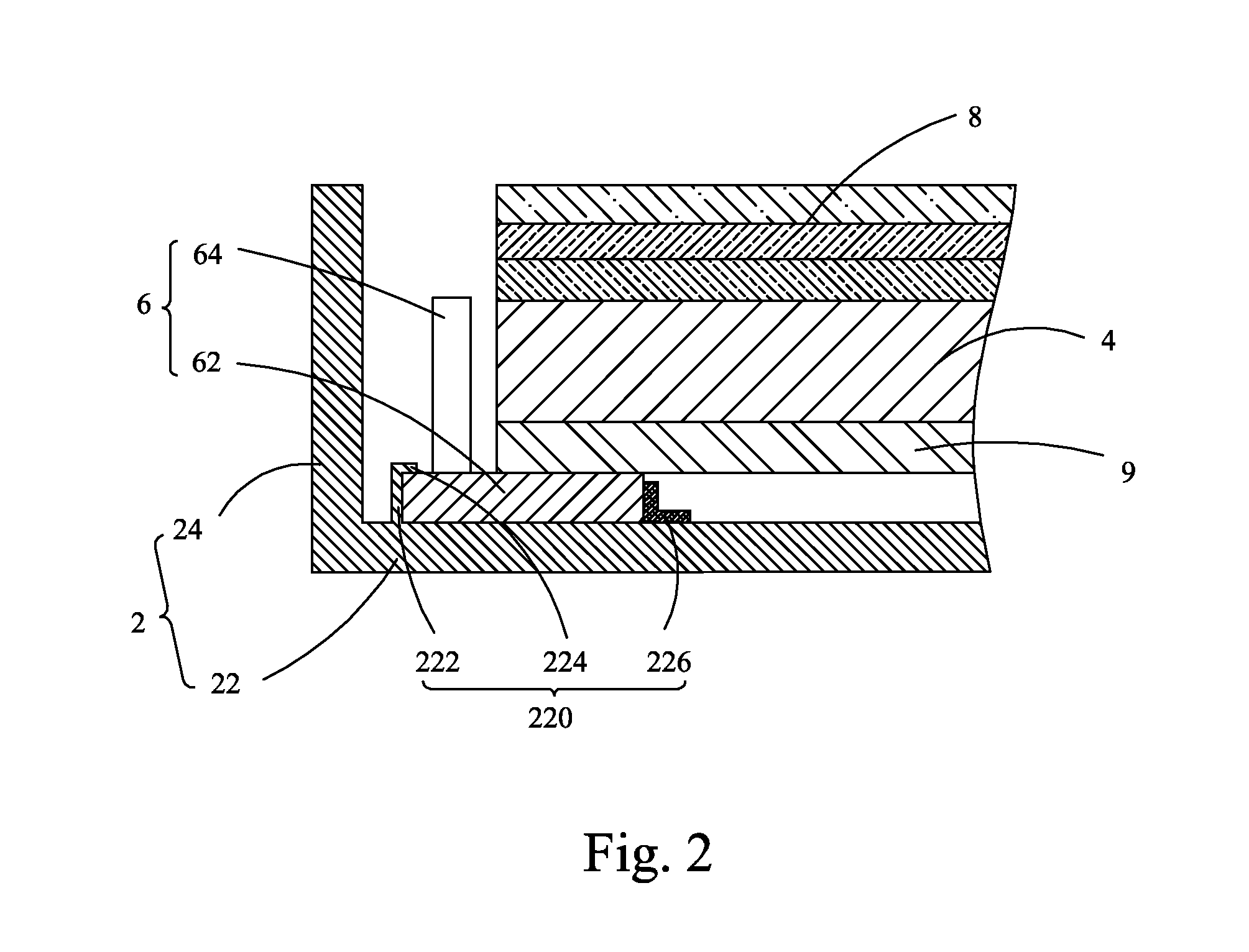
The present invention provides a backlight module and liquid crystal display device with a simple structure that ensures the mounting strength of a printed circuit board to improve the quality of the liquid crystal display device. The backlight module has a snap-engagement structure on the bottom plate of the backplane to securely mount the PCB, eliminating the use of fasteners and improving the strength of the PCB. This allows a reflection plate to be directly positioned on and supported by the PCB, helping achieve thinning of the liquid crystal display device and slimming of the device.

Problems solved by technology

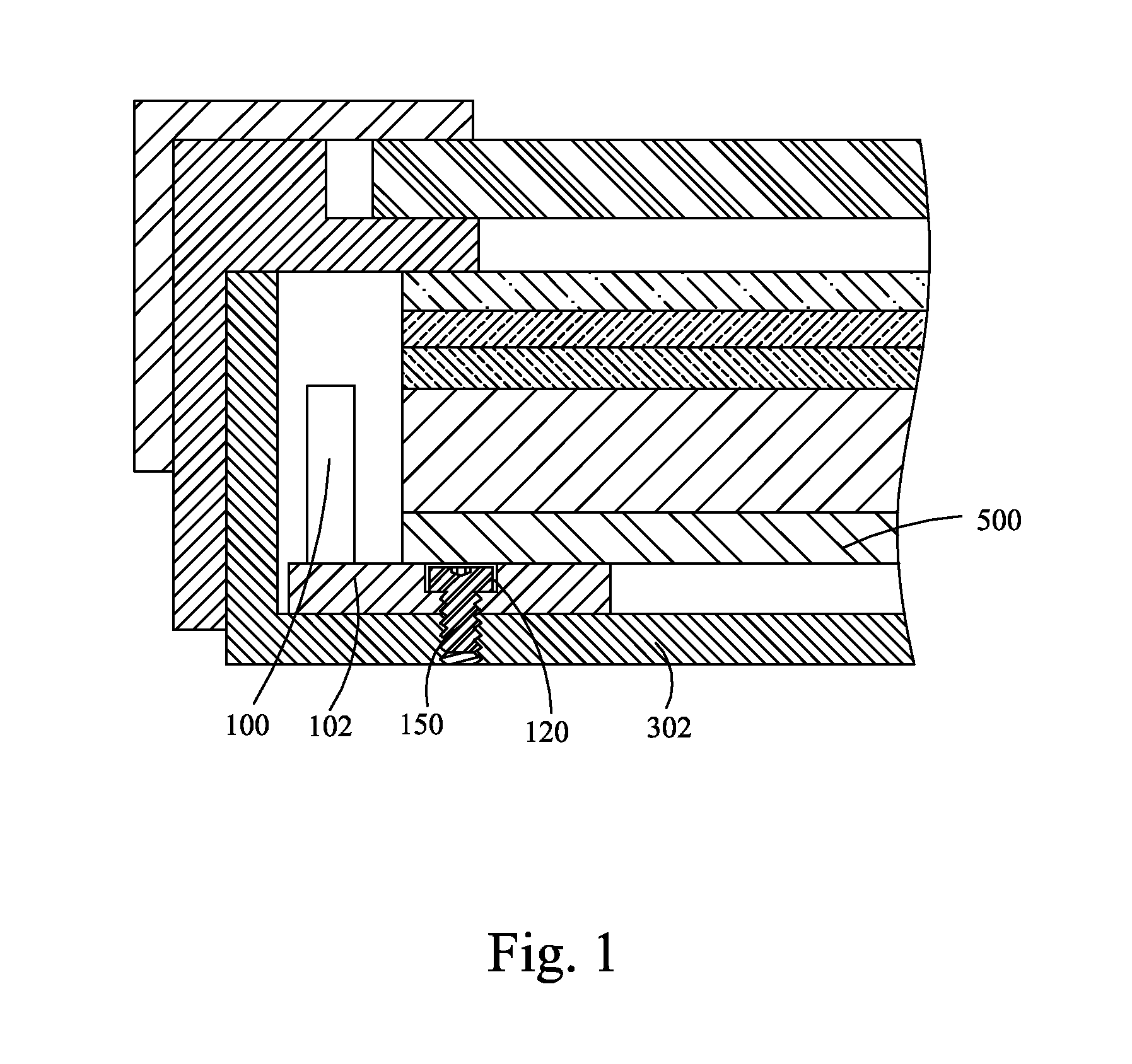
However, since the PCB 102 has a limited thickness, forming the stepped-configuration holes 120 in the PCB 102 may lead to deterioration of the strength of the PCB 102 so that the bolts 150 that are arranged in the PCB 102 may not securely fix the PCB 102 on the bottom plate 302 of the backplane and thus the quality of the liquid crystal display device is deteriorated.

Method used


Image

  • Backlight module and liquid crystal display device using same
  • Backlight module and liquid crystal display device using same
  • Backlight module and liquid crystal display device using same

Examples


Embodiment Construction

[0031]To further expound the technical solution adopted in the present invention and the advantages thereof, a detailed description is given to a preferred embodiment of the present invention and the attached drawings.

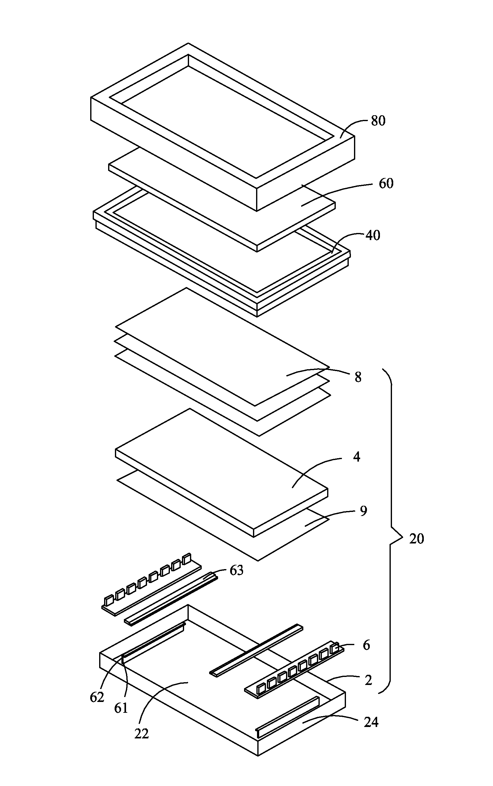
[0032]Referring to FIG. 2, the present invention provides a backlight module, which has a simple structure and specifically comprises: a backplane 2, a light guide plate 4 arranged in the backplane 2, a backlight source 6 arranged in the backplane 2, an optic film assembly 8 arranged above the light guide plate 4, and a reflection plate 9 arranged between the backplane 2 and the light guide plate 4. The backlight source 6 comprises a printed circuit board (PCB) 62 and a plurality of light-emitting diode (LED) lights 64 mounted on and electrically connected to the PCB 62. The backplane 2 comprises a bottom plate 22 and a plurality of side plates 24 perpendicularly connected to the bottom plate 22. The reflection plate 9 is arranged between the bottom plate 22 of the bac...


PUM

PropertyMeasurementUnit
elasticaaaaaaaaaa
structureaaaaaaaaaa
thicknessaaaaaaaaaa

Abstract

The present invention provides a backlight module and a liquid crystal display device using the backlight module. The backlight module includes: a backplane (2), a light guide plate (4) arranged in the backplane (2), a backlight source (6) arranged in the backplane (2), an optic film assembly (8) arranged above the light guide plate (4), and a reflection plate (9) arranged between the backplane (2) and the light guide plate (4). The backlight source (6) includes a PCB (62) and a plurality of LED lights (64) mounted on and electrically connected to the PCB (62). The backplane (2) includes a bottom plate (22) and a plurality of side plates (24) perpendicularly connected to the bottom plate (22). The bottom plate (22) of the backplane (2) includes a snap-engagement structure (220) formed thereon. The PCB (62) is snap-fit into and retained by the snap-engagement structure (220). The reflection plate (9) is directly positioned on and supported by the PCB (62).

Description

BACKGROUND OF THE INVENTION[0001]1. Field of the Invention[0002]The present invention relates to the field of liquid crystal displaying, and in particular to a backlight module and a liquid crystal display device using the backlight module.[0003]2. The Related Arts[0004]Liquid crystal displays have a variety of advantages, such as thin device body, low power consumption, and being free of radiation, and are thus widely used. Most of the liquid crystal displays that are currently available in the market are backlighting liquid crystal displays, which comprise a liquid crystal display panel and a backlight module. The operation principle of the liquid crystal display panel is that, with liquid crystal molecules interposed between two parallel glass substrates, a number of tiny vertical and horizontal electrical wires are arranged between the two glass substrates to selectively receive application of electricity thereto to control the rotation direction of the liquid crystal molecules ...

Claims


Application Information

Patent Timeline
Patent Type & Authority Applications(United States)
IPC IPC(8): F21V8/00G02F1/1335
CPCG02B6/0073G02F1/133615G02F1/133308G02F1/133605G02B6/0035G02F1/133608G02B6/0068G02B6/0083G02B6/009G02F2201/465G02F1/133314
Inventor YU, GANGHSIAO, YUCHUNCHEN, SHIHHSIANG
Owner TCL CHINA STAR OPTOELECTRONICS TECH CO LTD
Learn More