

Auto-tuning current loop compensation for power factor correction controller
a technology of power factor correction and compensation loop, which is applied in the direction of converting intermediate to dc, climate sustainability, and efficient power electronics conversion, etc., can solve the problems of reducing the operating life of transformers and induction motors of the system, failure of system protection circuits, and excessive heating
- Summary
- Abstract
- Description
- Claims
- Application Information
AI Technical Summary
Benefits of technology
Problems solved by technology
Method used
Image

Examples
Embodiment Construction
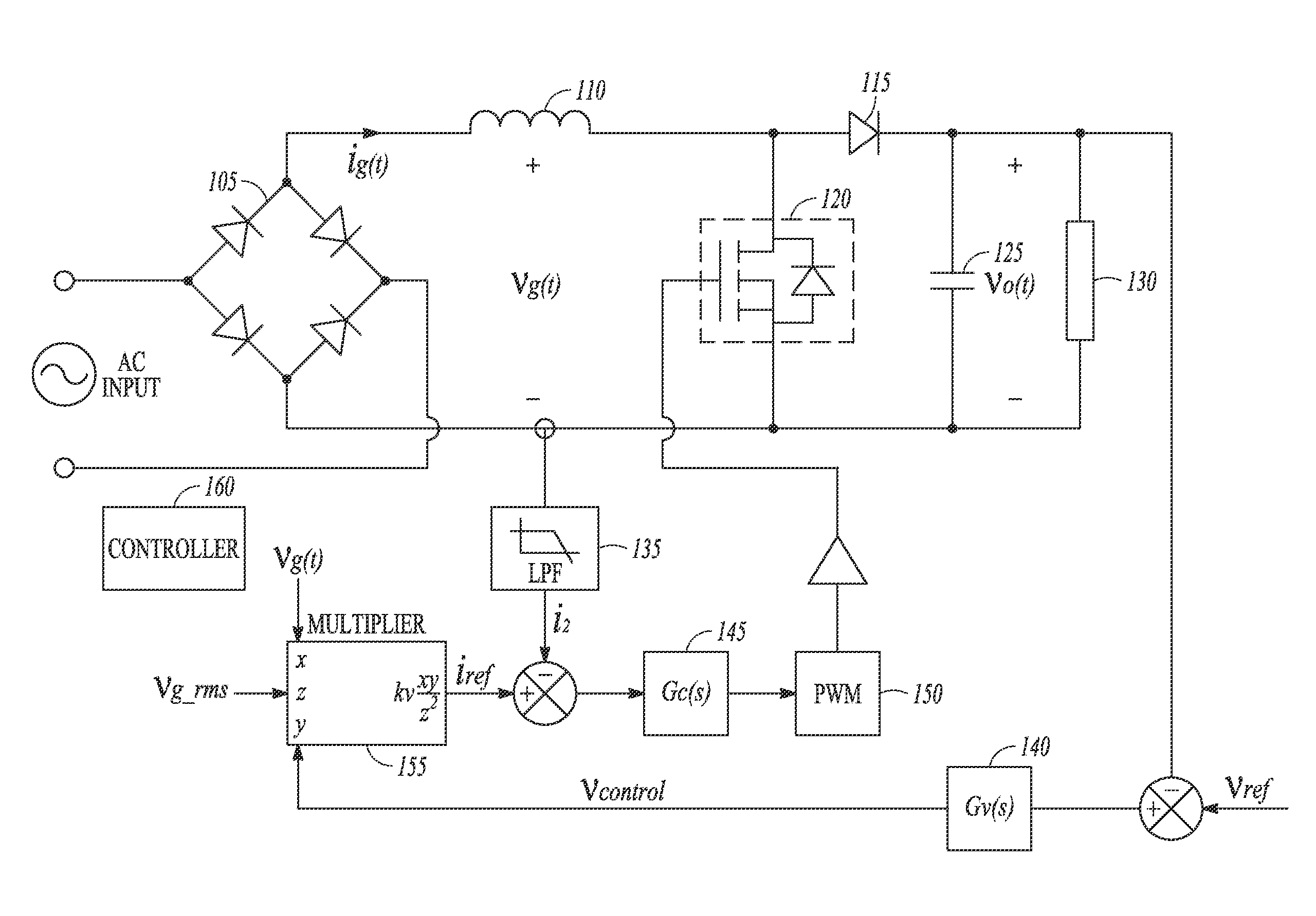
[0012]FIG. 1 shows a block diagram of an example of an AC to DC power converter circuit. The topology of the circuit is a boost converter with power factor correction (PFC). The boost converter topology provides flexibility in producing voltage conversion ratios, and provides lower total harmonic distortion (THD) and better transistor utilization than other topologies.
[0013]Power factor is a figure of merit for a rectifying circuit that reflects how effectively energy is transmitted between the source and load, and typically falls in the range of 1.0 to −1.0. Negative values of a power factor reflect an active load providing power to the input and are not considered herein. When the input voltage is sinusoidal and contains no harmonics, the power factor can be expressed as the product of two terms; the distortion factor and the displacement factor. The distortion factor is the ratio of the root-mean-square (RMS) value of the fundamental component of the line current to the RMS value...
PUM
 Abstract
Description
Claims
Application Information