Path-based floorplan analysis

a path-based and floor-plan technology, applied in the field of electronic design automation, can solve the problems of poor quality, long time-consuming and laborious floor-planning stage,

Active Publication Date: 2015-04-30
SYNOPSYS INC
View PDF2 Cites 3 Cited by
  • Summary
  • Abstract
  • Description
  • Claims
  • Application Information

AI Technical Summary

Benefits of technology

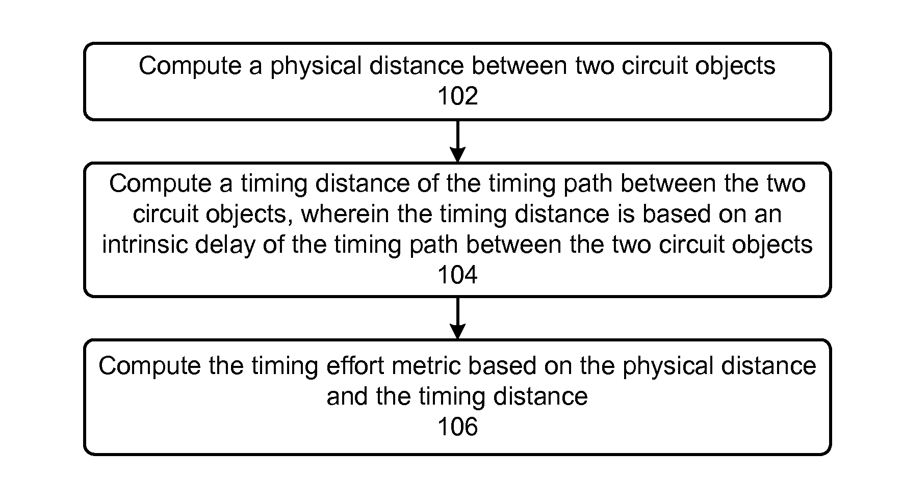
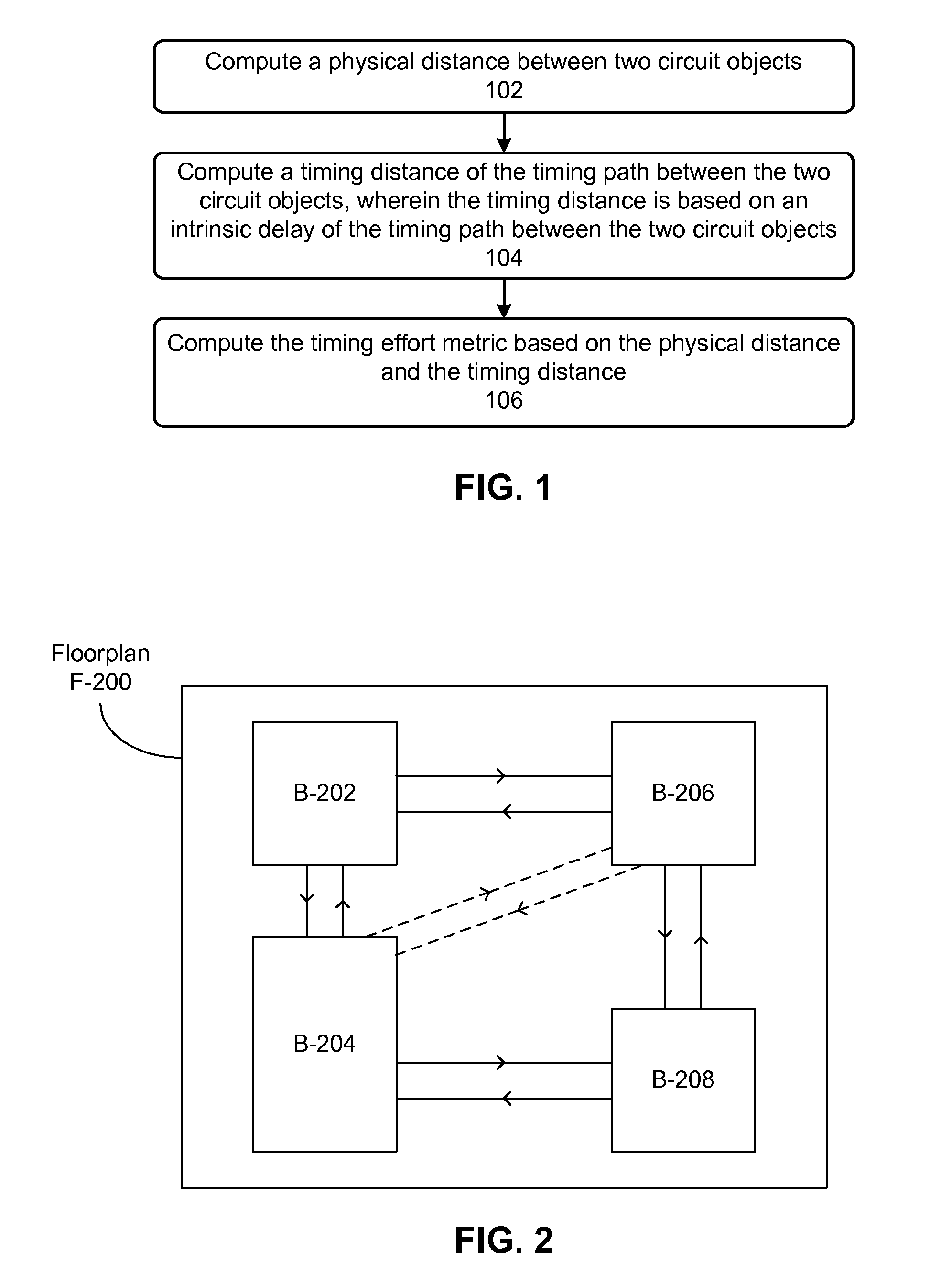
[0007]Some embodiments described herein provide methods and systems for predicting problems that a given floorplan might cause before t

Problems solved by technology

Unfortunately, due to the rapid increase in the size and complexity of IC designs, due to the stringent timing, area, and power budgets that are imposed on the IC designs, a

Method used


Image

  • Path-based floorplan analysis
  • Path-based floorplan analysis
  • Path-based floorplan analysis

Examples


Embodiment Construction

[0014]The following description is presented to enable any person skilled in the art to make and use the invention, and is provided in the context of a particular application and its requirements. Various modifications to the disclosed embodiments will be readily apparent to those skilled in the art, and the general principles defined herein may be applied to other embodiments and applications without departing from the spirit and scope of the present invention. Thus, the present invention is not limited to the embodiments shown, but is to be accorded the widest scope consistent with the principles and features disclosed herein.

Overview of an EDA flow

[0015]An EDA flow can be used to create a circuit design. Once the circuit design is finalized, it can undergo fabrication, packaging, and assembly to produce integrated circuit chips. An EDA flow can include multiple steps, and each step can involve using one or more EDA software tools. Some EDA steps and software tools are described b...


PUM


Abstract

Systems and techniques for computing a timing effort metric are described. According to one definition, the computed timing effort metric indicates a level of difficulty of fixing a timing violation associated with a timing path between two circuit objects in a circuit design layout.

Description

RELATED APPLICATION[0001]This application claims benefit of U.S. Provisional Application Ser. No. 61 / 895,795, by the same inventor, filed on 25 Oct. 2013, having attorney docket number SNPS-2396US01P, the contents of which are herein incorporated by reference in their entirety for all purposes.BACKGROUND[0002]1. Technical Field[0003]This disclosure relates to electronic design automation (EDA). More specifically, this disclosure relates to path-based floorplan analysis.[0004]2. Related Art[0005]Advances in process technology and a practically unlimited appetite for consumer electronics have fueled a rapid increase in the size and complexity of integrated circuit (IC) designs. The performance of EDA tools is very important because it reduces the time to market for IC designs. Floorplanning is an important stage in an EDA design flow that involves arranging relatively large circuit blocks (e.g., macros, memories, groups of smaller logic cells, etc.) within the area allotted to the cir...

Claims


Application Information

Patent Timeline
IPC IPC(8): G06F17/50
CPCG06F2217/84G06F17/5081G06F30/398G06F2119/12
Inventor SEGAL, RUSSELL B.
Owner SYNOPSYS INC
Why Eureka
Try Eureka