Redundantly tied metal fill for IR-drop and layout density optimization

a technology of layout density and metal fill, applied in the direction of cad circuit design, semiconductor/solid-state device details, instruments, etc., can solve the problems of redundant connection of metal fill geometries and seek partially redundant connectivity, so as to reduce the voltage drop in the power mesh, avoid excessive increase in the number of metal fill, and reduce the effect of ir drop

Active Publication Date: 2007-07-03
SYNOPSYS INC
View PDF9 Cites 113 Cited by
  • Summary
  • Abstract
  • Description
  • Claims
  • Application Information

AI Technical Summary

Benefits of technology

[0010]The present invention advantageously uses tied metal filling to reduce the voltage drop in a power mesh by introducing redundancy. Floating metal fill geometries are redundantly connected to the power mesh whenever possible, by adding vias or by making same-layer “bridge” connections, while ensuring design-rule correctness. Furthermore, metal fill geometries are redundantly connected to neighboring metal fill geometries to establish additional connectivity between power mesh geometries. While the system seeks maximally redundant connectivity between metal fill geometries and power mesh geometries, the system only seeks partially redundant connectivity between metal fill geometries and other metal fill geometries. This is done to avoid excessive increase in the number of metal fill geometries introduced.
[0011]The redundancy adds more pathways for current flow between different points of the power mesh, hence reducing IR drop by reducing the effective resistance on a power mesh. Thus, the present invention advantageously uses metal fill geometries to reduce the voltage drop in a power mesh, and concurrently satisfies the IR drop requirements and the layout density requirements.

Problems solved by technology

Furthermore, metal fill geometries are redundantly connected to neighboring metal fill geometries to establish additional connectivity between power mesh geometries.
While the system seeks maximally redundant connectivity between metal fill geometries and power mesh geometries, the system only seeks partially redundant connectivity between metal fill geometries and other metal fill geometries.

Method used


Image

  • Redundantly tied metal fill for IR-drop and layout density optimization
  • Redundantly tied metal fill for IR-drop and layout density optimization
  • Redundantly tied metal fill for IR-drop and layout density optimization

Examples


Embodiment Construction

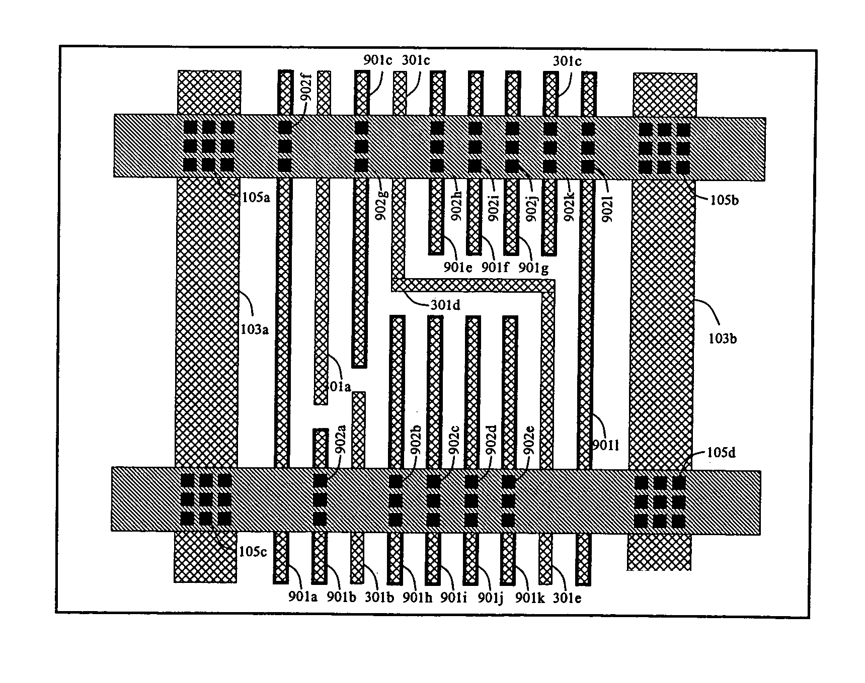
[0055]A preferred embodiment of the present invention is now described with reference to the figures where like reference numbers indicate identical or functionally similar elements and where depicted elements are not necessarily shown to scale. Also in the figures, the left most digit(s) of each reference number typically correspond(s) to the figure in which the reference number is first used.

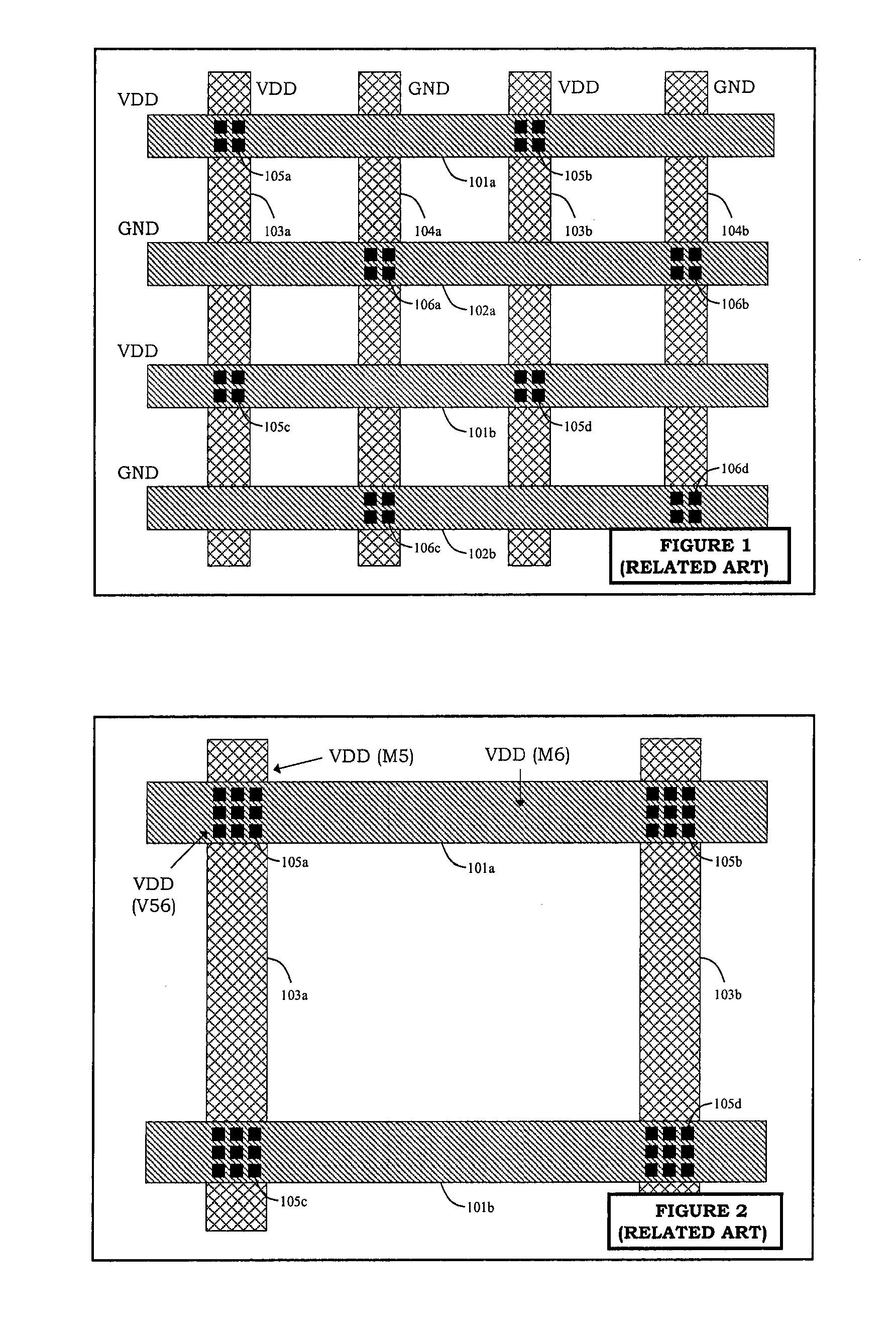
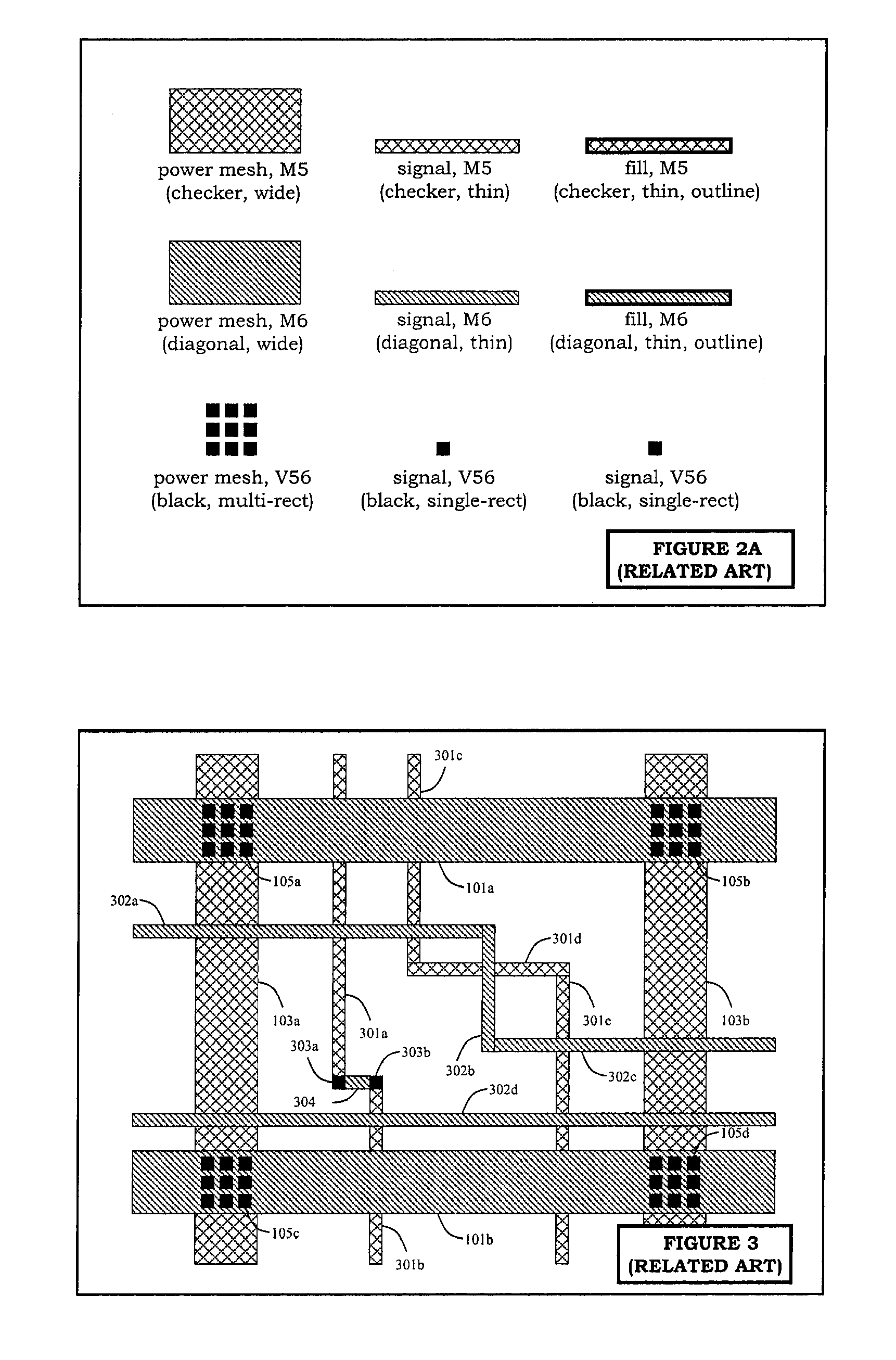
[0056]Integrated devices are interconnected in electronic circuits with each other using metal layers in horizontal planes above the integrated devices. These metal layers (or levels), up to twelve or more, are referred to M1, M2, M3, etc. and facilitate signal routing and power distribution. The intermediate layers between metal layers are called via layers, and are referred to as V12, V23, V34, etc. For example, V12 is between M1 and M2. Those skilled in the art will recognize that power mesh conductors, signal conductors and fill metals described herein can be made of conductive material, f...


PUM


Abstract

An integrated circuit and a method for using metal fill geometries to reduce the voltage drop in power meshes. Metal fill geometries are connected to the power mesh using vias or wires at multiple locations. Metal fill geometries are connected to other floating metal fill geometries using vias or wires at multiple locations. The circuit design introduces maximum redundancy between metal fill geometries and power mesh geometries, but partial redundancy between metal fill geometries and metal fill geometries. In particular, the redundancy in connectivity between metal fill geometries and metal fill geometries is kept minimal to reduce the number of geometries introduced. The high redundancy between metal fill geometries and power mesh geometries and the partial redundancy among metal fill geometries result in a smaller IR-drop by reducing the effective resistance on a power mesh. Hence, the invention use redundancy carefully and advantageously to achieve simultaneous metal density and IR-drop optimization without introducing excessive number of metal fill geometries.

Description

BACKGROUND OF THE INVENTION[0001]1. Field of the Invention[0002]The present invention relates generally to the design of semiconductor integrated circuits (“ICs”) and more specifically, to using redundantly tied metal fill for voltage drop (as a function of current and resistance, also referred to as “IR-drop”) and layout density optimization.[0003]2. Background of the Invention[0004]Semiconductor integrated circuits (ICs) are typically composed of layer structures consisting of several layers of conducting, insulating and other materials. These materials are structured in the horizontal dimension by fabrication processes that transfer patterns defined in physical designs or layouts. Further, IC design processes typically employ various rules to ensure uniform density requirements and signal integrity requirements.[0005]The multilayer interconnect in ICs allow various transistors to be connected to complete a circuit. In the metal layers of an IC chip, there are some areas with high...

Claims


Application Information

Patent Timeline
Patent Type & Authority Patents(United States)
IPC IPC(8): G06F17/50
CPCG06F17/5068H01L23/5286H01L2924/3011H01L2924/0002H01L2924/00G06F30/39
Inventor LEUNG, HARDY KWOK-SHING
Owner SYNOPSYS INC
Why Eureka
Try Eureka