

Light divider and magnetism measurement apparatus
- Summary
- Abstract
- Description
- Claims
- Application Information
AI Technical Summary
Benefits of technology
Problems solved by technology
Method used
Image

Examples
first embodiment
1. First Embodiment
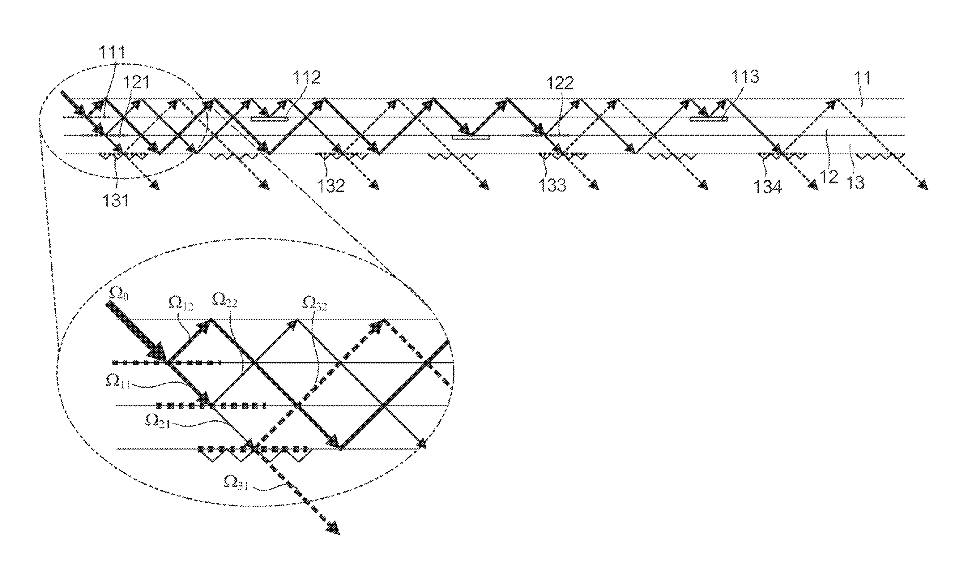
[0027]FIG. 1 shows the configuration of a light divider 1 according to a first embodiment. The light divider 1 is an apparatus that divides a single light flux incident thereon into a plurality of light fluxes. The first embodiment relates to a case where incident light is divided into eight light fluxes. FIG. 1 is a diagrammatic view of a cross section viewed along a direction perpendicular to the optical path of the incident light. The incident light is outputted from a light source (not shown). The light source includes, for example, a semiconductor laser diode. Since laser light typically has a Gaussian intensity distribution, a beam homogenizer may be used to homogenize the intensity distribution of the outputted light.
[0028]The light divider 1 has three substrates (substrate 11, substrate 12, and substrate 13) that serve as a light guide. Each of the substrates is a flat plate having surfaces parallel to each other and made of a light transmissive material (...
second embodiment
2. Second Embodiment
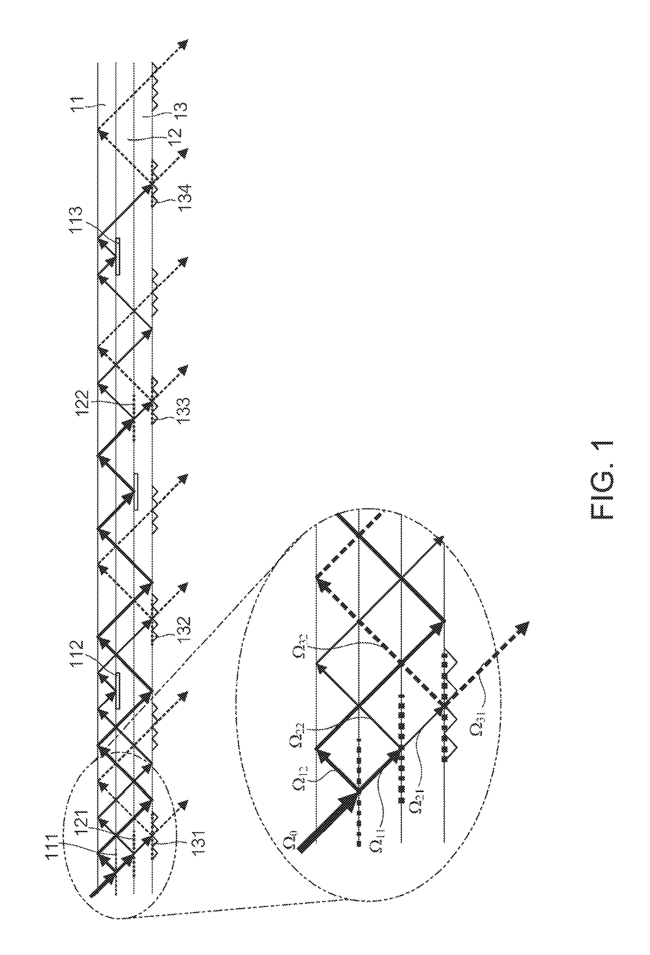
[0041]FIG. 2 shows the configuration of a light divider 2 according to a second embodiment. Elements common to those in the light divider 1 will not be described below. In the light divider 1, the structural components (triangular prisms, for example) are provided on a light extracting portion basis, whereas in the light divider 2, structural components are provided over the entire lower surface of the light guide. Further, total reflection films that totally reflect light fluxes (total reflection films 151 to 154) are formed on the lower surface of the light guide in the portions excluding the light extracting portions. The total reflection films are not necessarily provided on the lower surface of the light guide over the entire portions excluding the light extracting portions but only need to be provided on at least part of the portions excluding the light extracting portions (specifically, portions where light fluxes are desired to be totally reflected).
[0042...
third embodiment
3. Third Embodiment
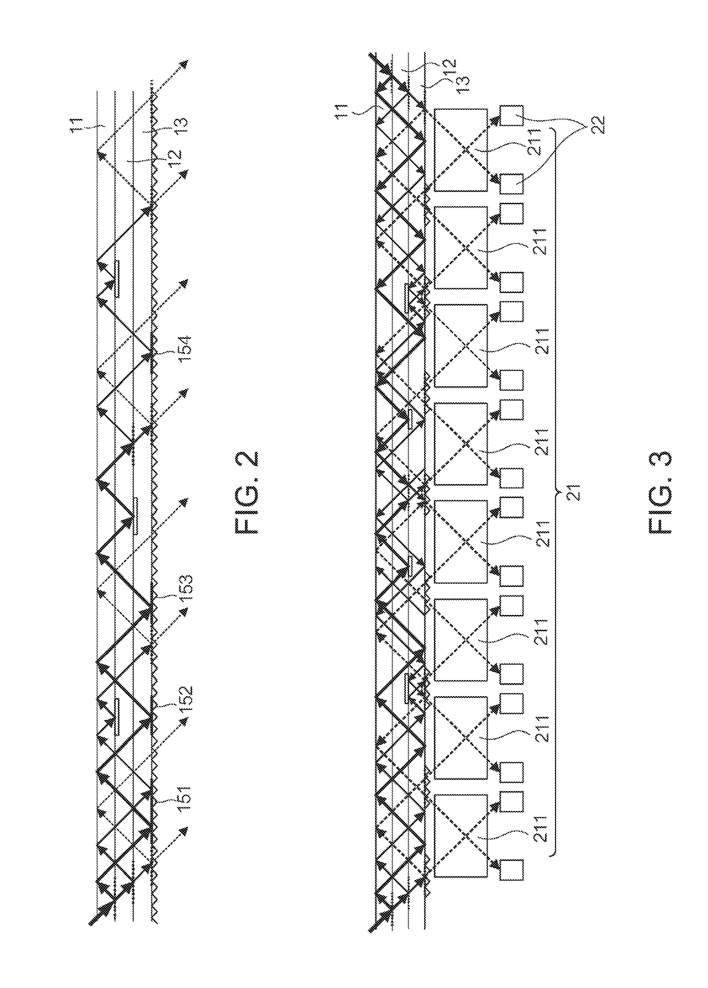
[0043]FIG. 3 shows the configuration of a magnetism measurement apparatus 10 according to a third embodiment. In this example, the magnetism measurement apparatus 10 uses nonlinear magneto-optical rotation (NMOR). The magnetism measurement apparatus 10 includes a light divider 3 and a sensor array 20.
[0044]The light divider 3 has the same configuration as that of the light divider 1 but differs therefrom in that an incident light flux is incident on the right and left sides of the plane of view and each of the two incident light fluxes is divided into eight light fluxes. In this example, some of the light extracting portions are used for the two incident light fluxes. Specifically, nine light extracting portions are used as follows: The leftmost one is dedicated for the incident light flux from left; the rightmost one is dedicated for the incident light flux from right; and the other light extracting portions are common to the two incident light fluxes.
[0045]The s...
PUM
 Abstract
Description
Claims
Application Information