Tray for an exposure machine

a technology of exposure machine and exposure tube, which is applied in the direction of electrical equipment, instruments, printing, etc., can solve the problems of small depth of field, insufficient suction force, and insufficient suction force to correct panel curvature,

Active Publication Date: 2015-05-07
ALTIX
View PDF6 Cites 1 Cited by
  • Summary
  • Abstract
  • Description
  • Claims
  • Application Information

AI Technical Summary

Benefits of technology

[0040]In certain embodiments, the force applicator is an oblong strip extending in the first direction or the second direction, respectively. This shape enables it to press against a long length of the edge of the panel. Where appropriate, it also makes it possible to press the corners of the panel down effectively against the work surface.
[0041]In certain embodiments, the position of the force applicator in the rest state is higher and further out than its position in the holding state. In this way, it is possible to use panels of different thicknesses without running the risk of the force applicator coming into abutment against the edge face of the panel while moving towards the holding state. In addition, in the rest state, this makes it possible to allow the panel to pass under while it is being loaded or unloaded.
[0042]In certain embodiments, the actuator device of at least one holder device of the first type comprises a first actuator configured to lift or lower the force applicator and a second actuator configured to cause the force applicator to advance or retreat laterally. Since these two actuators are distinct, each of them is dedicated to one specific task that it can carry out effectively and independently of the behavior of the other actuator. Thus, by way of example, the horizontal position of the force applicator in its holding state can be correct regardless of the thickness of the panel. Likewise, the force used by the first actuator can serve solely for preventing the panel from moving.

Problems solved by technology

Nevertheless, such exposure heads having a matrix of micro-mirrors, which constitute the technology that is in the most widespread use in the direct imaging technique, present the defect of possessing depths of field that are small, typically of the order of 300 micrometers (μm).
Nevertheless, such suction devices are not sufficient for achieving the degree of planeness that is required for such depths of field.
Certain panels, in particular for printed circuits, can be very thick, having thickness of the order of several millimeters, and thus very rigid: under such circumstances, if the panel is slightly warped, the suction force is not sufficient for correcting such curvature of the panel.
Panels that are thin and flexible, e.g. the inner layers of printed circuits or indeed the panels used for flexible screens or for chemical etching, also present significant problems when they have curled corners: because of the large distance between a curled portion of the panel and the suction device, the suction device cannot take hold of that portion of the panel effectively.
Furthermore, with panels that are thick or thin, certain suction nozzles are constrained under such circumstances to suck in air without opposition, thereby weakening the suction force at all of the neighboring nozzles forming part of a common array, and thus reducing the extent to which the panel is pressed down over a large area.
Nevertheless, that solution presents ergonomic problems for the operator in charge of loading panels.
That uncomfortable position is made worse when the panel is small and therefore needs to be placed a long way from the edge.
It can naturally be understood that this leads to arduous working conditions for the operator, e.g. running a risk of musculoskeletal disorders.
In addition, centering the panel on the table, which must be accurate in order to ensure that the projected image is aligned correctly with the panel, requires the operator to adjust the position of the panel in translation along two different directions, and also in rotation about the vertical axis, where this is made that much more difficult to perform, specifically because the panel is situated at a distance from the operator: the accuracy with which the panel is positioned is thus relatively poor, and that can give rise to problems of alignment with the exposure head.

Method used


Image

  • Tray for an exposure machine
  • Tray for an exposure machine
  • Tray for an exposure machine

Examples


Embodiment Construction

)

[0069]In order to make the invention more concrete, an example of a tray and an exposure machine is described in detail below with reference to the accompanying drawings. It should be recalled that the invention is not limited to this example.

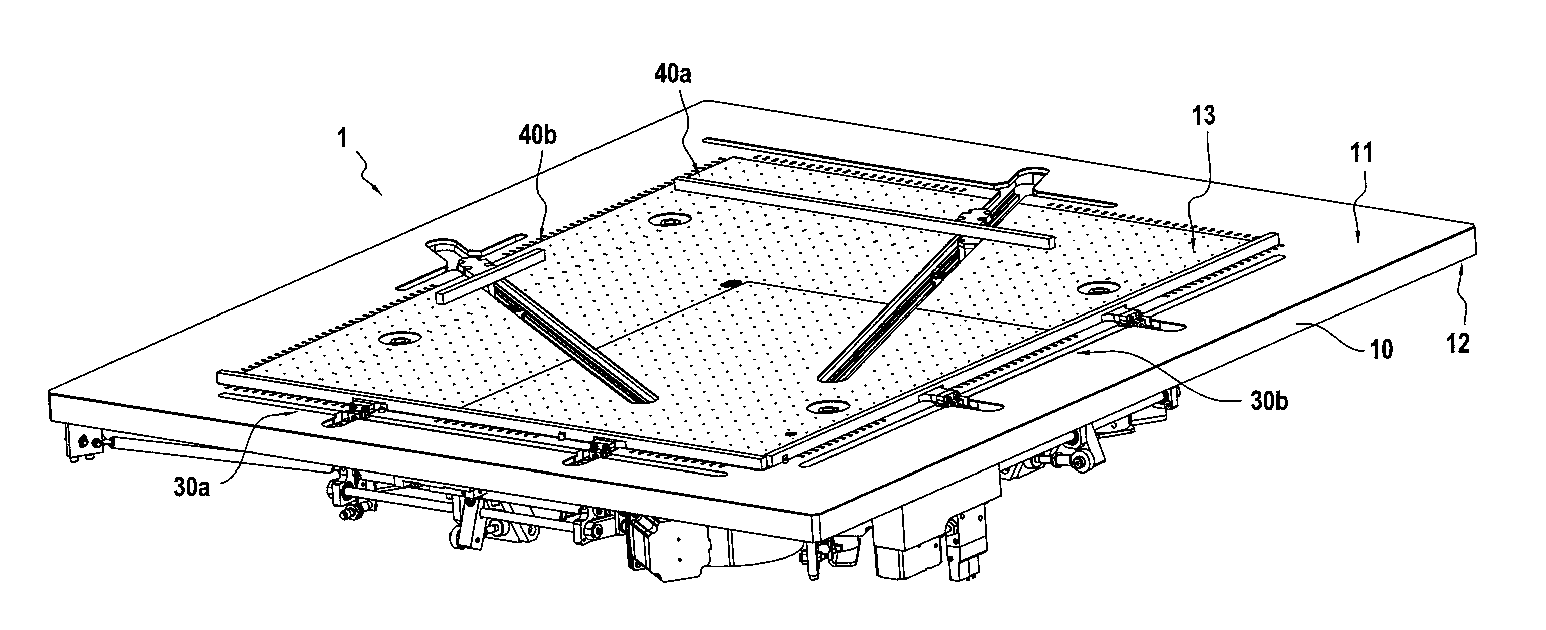
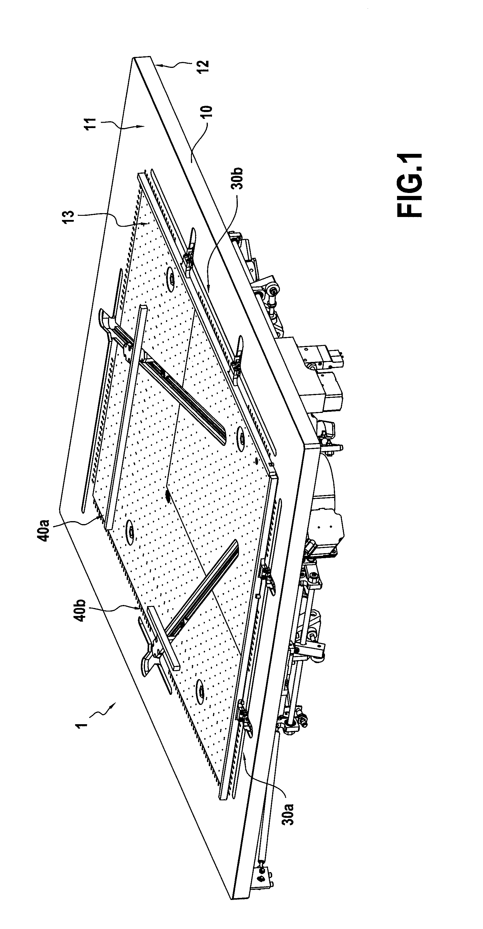
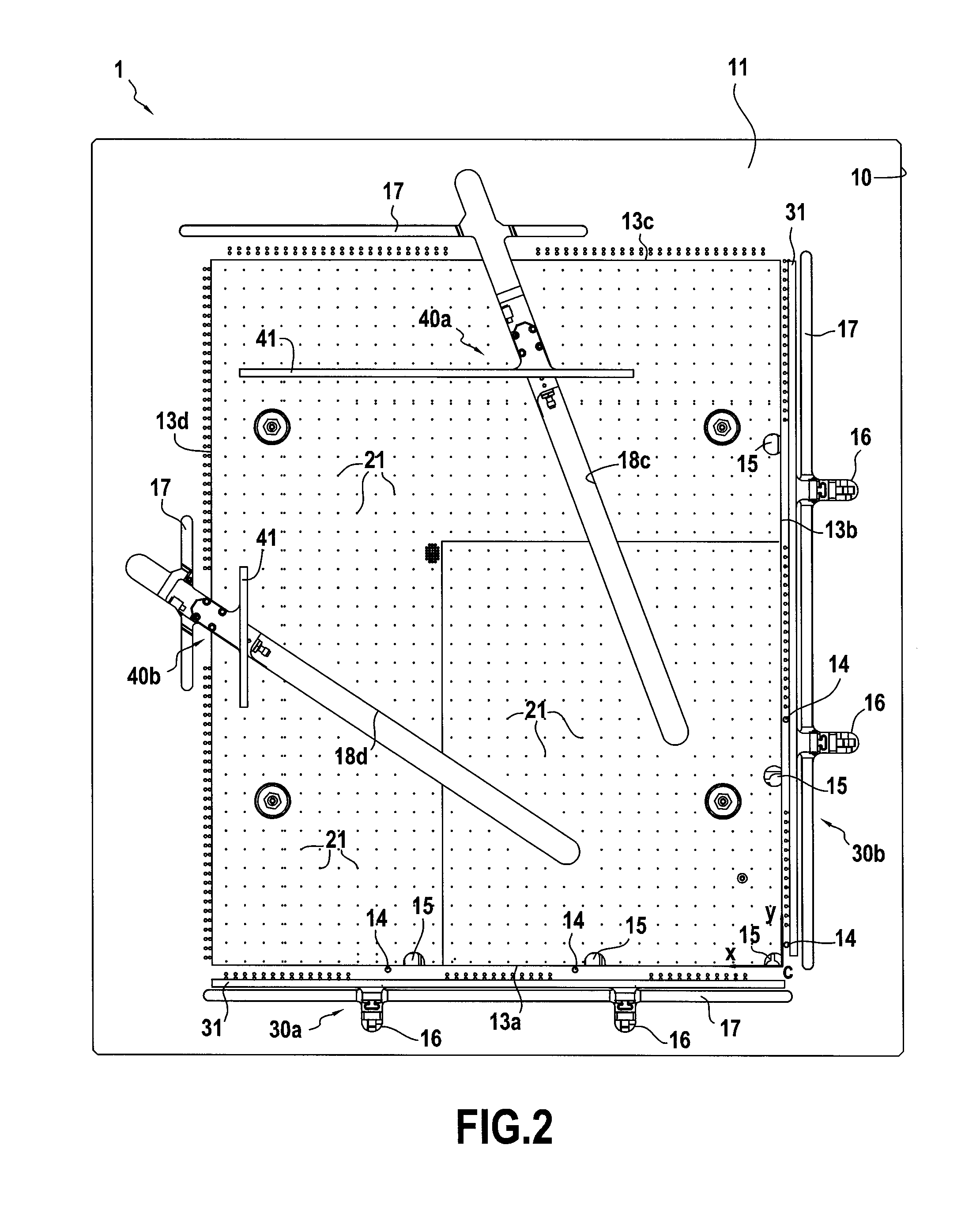
[0070]FIGS. 1 and 2 show an example tray 1 of the invention. This tray 1 comprises a frame 10 that is substantially in the form of a rectangular parallelepiped having a top face 11 and a bottom face 12. In order to minimize the weight of the tray, and thus its inertia in motion, the frame is of small thickness, less than 30 millimeters (mm), and its bottom surface 12 presents reinforcing ribs providing the tray 1 with overall stiffness and ensuring that its top surface 11 is plane, which surface should be plane to within tolerance of less than 200 μm. These reinforcing ribs also serve to fasten auxiliary devices to the bottom surface 12 of the frame 10.

[0071]The top surface 11 of the frame 10 presents a rectangular zone extending in two orthog...


PUM

PropertyMeasurementUnit
angleaaaaaaaaaa
angleaaaaaaaaaa
angleaaaaaaaaaa

Abstract

A tray for a panel exposure machine, and also such a machine, enabling a panel to be retained and pressed down so as to be presented facing an exposure device. The tray comprises a work surface (13) adapted to receive panels of different sizes, said work surface (13) being substantially plane and possessing first and second adjacent edges (13a, 13b) extending along substantially orthogonal first and second directions (X, Y) defining a reference corner (C); and first and second holder devices (30a, 30b) of a first type and at least a first holder device (40a) of a second type, each holder device being actuatable between a holding, first state in which it exerts pressure directed towards the work surface (13), thereby defining a holding position, and a rest, second state in which said pressure is released; a positioning device (14) arranged along at least a portion of the first edge (13a) and along at least a portion of the second edge (13b); the holder devices (30a, 30b) of the first type extend along at least a portion of the first and second edges (13a, 13b) respectively, their holding positions being fixed in a plane parallel to the work surface; the holder device (40a) of the second type is movable in a plane parallel to the work surface (13) in order to adapt its holding position as a function of the size of the panel in use.

Description

CROSS-REFERENCE TO RELATED APPLICATIONS[0001]This application claims priority under 35 U.S.C. §119 to French Patent Application No. 1360868, filed Nov. 6, 2013, which is incorporated herein by reference in its entirety.FIELD OF THE INVENTION[0002]The present description relates to a tray for a panel exposure machine, and also to such a machine, the tray enabling a panel to be retained and pressed down in order to enable it to be presented facing an exposure device.[0003]The field of application of the invention is mainly that of printed circuits, however the invention can also be used in any field making use of image transfer methods, such as the field of liquid crystal display (LCD) screens, touch screens, photovoltaic cells, or indeed the field of fabricating micromechanical parts by chemical etching.STATE OF THE PRIOR ART[0004]Among techniques for exposing panels and transferring images, the so-called “direct imaging” technique possesses the advantage of not using a physical imag...

Claims


Application Information

Patent Timeline
Patent Type & Authority Applications(United States)
IPC IPC(8): G03F7/20
CPCG03F7/70716G03F7/20G03F7/707G03F7/70825H01L21/68728H05K3/0008H05K2203/0165
Inventor LEBOUCHER, ARNAUD R.
Owner ALTIX
Why Eureka
Try Eureka