Power source device, electric vehicle provided with same, and electricity storage device

a technology of power source device and electric vehicle, which is applied in the direction of battery/fuel cell control arrangement, cell components, battery/fuel cell, etc., can solve problems such as gas leakage, and achieve the effect of preventing the damage of the broken piece of the gas exhaust valve in the external gas exhaust duct, facilitating the opening movement of the gas exhaust valve, and ensuring the safety of the user

Inactive Publication Date: 2015-05-07
SANYO ELECTRIC CO LTD
View PDF6 Cites 44 Cited by
  • Summary
  • Abstract
  • Description
  • Claims
  • Application Information

AI Technical Summary

Benefits of technology

[0007]The present disclosure is developed for the purpose of solving such drawbacks. One non-limiting and explanatory embodiment provides a power supply device, and a vehicle and a storage battery device equipped with the power supply device in which even though a gas exhaust valve breaks, the trouble by a broken piece is prevented.
[0008]A power supply device of the present disclosure comprises a battery cell comprising an outer can, and a gas exhaust valve opening a part of the outer can in response to becoming a high pressure in the inside of the outer can, a gas duct guiding the gas exhausted from the gas exhaust valve to an external gas exhaust duct, and the gas exhaust valve is integrally coupled to the outer can at the time of opening the gas exhaust valve, and the connecting portion between the outer can and the gas exhaust valve is partially broken at the time of opening the gas exhaust valve by an internal pressure of the outer can, and the gas duct further comprises a joining aperture being connected airtight to the gas exhaust valve, and a duct exhaust portion being connected to the external gas exhaust duct, and the inner diameter inside the gas duct is at least partially smaller than the outer diameter of the gas exhaust valve between the joining aperture and the duct exhaust portion. Accordingly, when the broken piece broken by the high pressure gas intrudes into the gas duct, it is prevented that the broken piece is exhausted into the external gas exhaust duct. As a result, even when the external gas exhaust duct is made of, for example, a tube of rubber or the like, the damage in the external gas exhaust duct by the broken piece of the gas exhaust valve can be prevented.
[0011]Furthermore, in the power supply device of the present disclosure, the outer can has a tubular shape of a rectangle in a sectional view having a bottom portion, and an opening at the top portion, and the opening of the outer can is closed by a sealing plate made of metal, and the gas exhaust valve is the metal board which is made as a thin portion in a part of the sealing plate, and the gas exhaust valve opens by the metal board being broken from the sealing plate at the time of increasing the internal pressure of the outer can. Accordingly, when the broken piece broken by the high pressure gas intrudes into the gas duct, it is prevented that the broken piece is exhausted into the external gas exhaust duct. As a result, even when the external gas exhaust duct is made of, for example, a tube of rubber or the like, the damage in the external gas exhaust duct by the broken piece of the gas exhaust valve can be prevented. Further, it is prevented that the broken metal piece exhausted from the gas duct unintentionally makes an electrical circuit short by contacting the electrical circuit.
[0012]Furthermore, in the power supply device of the present disclosure, in the sealing plate, an elongated hole is formed in a state of the gas exhaust valve opening, and the gas exhaust valve is formed as the thin portion in the sealing plate at the center in the elongated direction in a state of the gas exhaust opening being closed, and in response to becoming a high pressure in the inside of the outer can, the center of the gas exhaust valve is broken, and the gas exhaust valve opens toward outside the outer can. Accordingly, an opening movement of the gas exhaust valve is simplified and surely carried out in response to the increase of the internal pressure.

Problems solved by technology

In this case, the broken metal board can be conveyed by the gas pressure from the gas duct to the external gas exhaust duct, and the inner surface of the tube made of rubber is damaged by a sharp broken metal board, and then a gas leakage might happen.

Method used


Image

  • Power source device, electric vehicle provided with same, and electricity storage device
  • Power source device, electric vehicle provided with same, and electricity storage device
  • Power source device, electric vehicle provided with same, and electricity storage device

Examples


embodiment 1

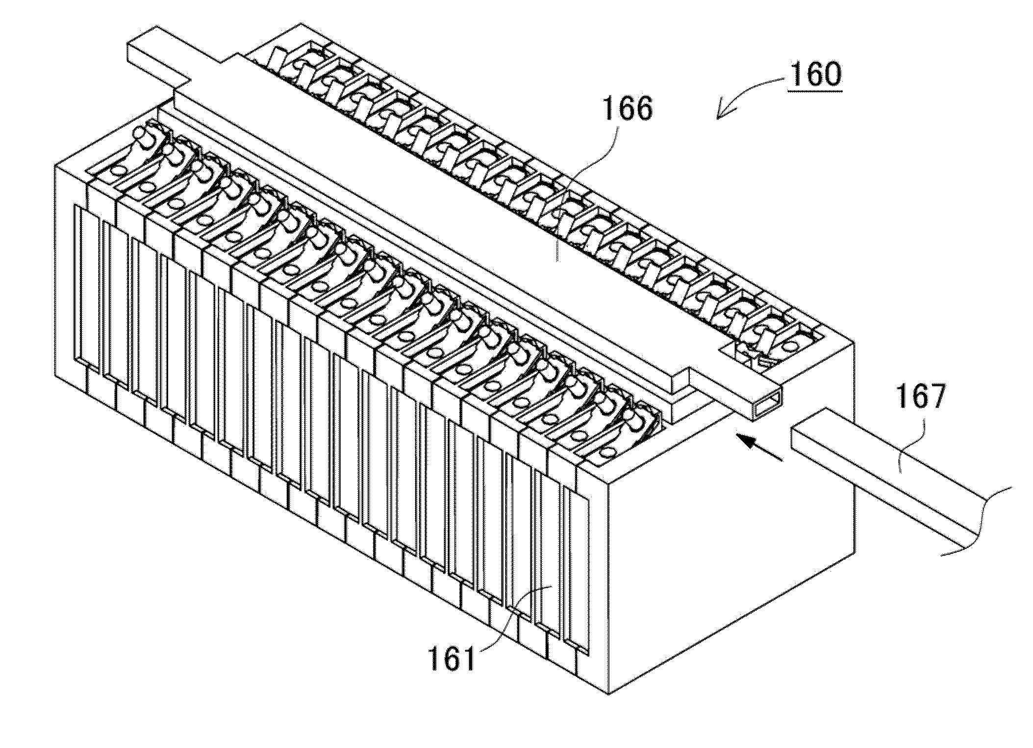
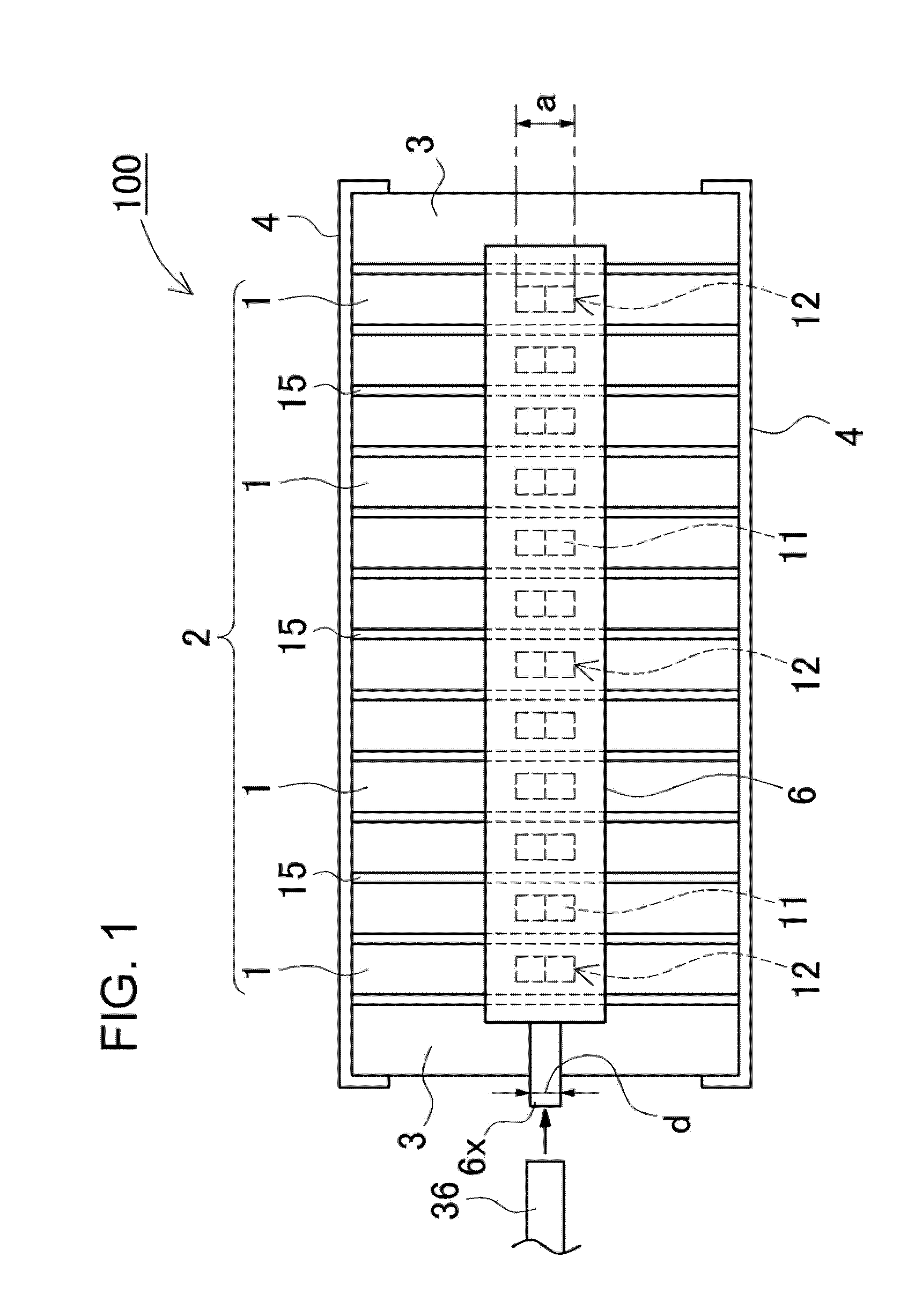
[0037]A schematic view of a power supply device 100 related to an embodiment 1 of the present invention, is shown in FIG. 1. The power supply device 100 shown in this figure comprises a battery stacked member 2 in which plural battery cells 1 are stacked, and a gas duct 6. In the battery stacked member 2, plural sheets of the battery cells 1 are stacked interposing spacers 15, and end plates 3 are disposed at both end surfaces, and then the end plates 3 are bound by binding members 4. The spacers 15 are made of insulating material in order to insulate the battery cells 1 from each other. Further, the end plates 3 are made of high rigidity material, for example, metal or the like in order to bind the battery stacked member 2 in a stacked state. In addition, in the same way, the binding members 4 are made of high rigidity material, for example, metal or the like. Here, in each of the binding members 4, a metal board is bent in a U-shaped cross-sectional shape, and end portions of the ...

embodiment 2

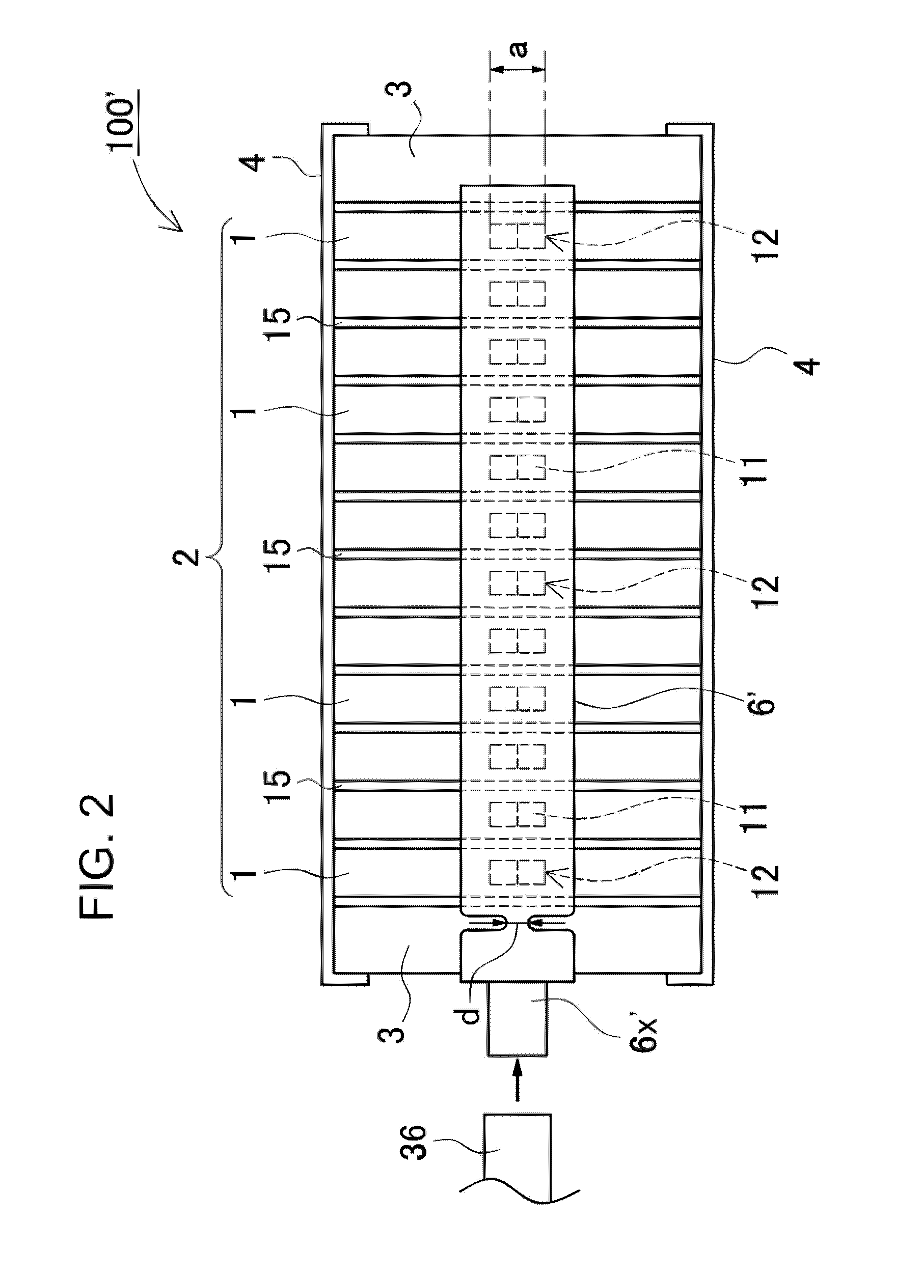
[0047]The above embodiment explains a case that the inner diameter d of the duct exhaust portion 6x at the end portion of the gas duct 6 is smaller than the outer diameter a of the gas exhaust valve 11. However, it is not necessarily limited to this position, and the middle in the tubular channel of the gas duct can be narrow, and in the same way, the damage in the external gas exhaust duct of a tube made of rubber or the like by piece of metal board can be prevented. For example, as shown in FIG. 2 as the embodiment 2, a part of a gas duct 6′ is partially narrowed, and the inner diameter d becomes small in this portion, and then the exhaust of piece of metal board is prevented. According to this structure, the exhaust of piece of metal is effectively prevented without the inner diameter of a duct exhaust portion 6x′changed.

embodiment 3

[0048]Further, regarding the narrowed shape, besides the outer shape of the gas duct of itself being narrowed, as shown in the embodiment 3 of FIG. 3, an inner portion of a gas duct 6″can be narrowed. By this structure, only the inner portion of the inner diameter d is partially narrowed without the outer shape of the gas duct 6″changed, a decrease of strength in the gas duct 6″can be prevented. The inner diameter of a duct exhaust portion 6x″ is also unchanged in the same as the embodiment 2. Thus, being not limited to the end portion of the gas duct, at least a part of the inner portion in the tubular channel of the gas duct is narrowed, and then it is prevented that the gas exhaust valve 11 is exhausted outside from the gas duct.

[0049]As mentioned above, the exit or the middle in the tubular channel of the gas duct, namely at between the joining aperture and the duct exhaust portion, by providing a gas duct portion in which the inner diameter of the gas duct is smaller than the o...


PUM

PropertyMeasurementUnit
pressureaaaaaaaaaa
internal pressureaaaaaaaaaa
inner diameteraaaaaaaaaa

Abstract

In a power supply device, the gas exhaust valve is integrally coupled to the outer can at the time of opening the gas exhaust valve, and the connecting portion between the outer can and the gas exhaust valve is partially broken at the time of opening the gas exhaust valve by an internal pressure of the outer can, and the gas duct further comprises a joining aperture being connected airtight to the gas exhaust valve, and a duct exhaust portion being connected to the external gas exhaust duct, and the inner diameter d inside the gas duct is at least partially smaller than the outer diameter a of the gas exhaust valve between the joining aperture and the duct exhaust portion.

Description

CROSS-REFERENCE TO RELATED APPLICATIONS[0001]The present application is a national stage application of international application PCT / JP2013 / 004658 filed on Aug. 1, 2013, and claims the benefit of foreign priority of Japanese patent application 2012-176717 filed on Aug. 9, 2012, the contents both of which are incorporated herein by reference.TECHNICAL FIELD[0002]The present invention relates to a power source device having a plurality of stacked battery cells, and to a vehicle and a storage battery device equipped with the power source device, in particular, to a power source device for a motor driving installed in an electric vehicle such as a hybrid vehicle, fuel-cell vehicle, electric vehicle, or electric auto-bike, or to a power source device configured to supply high current such as in a home or industrial power storage application, and a vehicle and a storage battery device equipped with the power source device.BACKGROUND ART[0003]A power supply device having plural battery ce...

Claims


Application Information

Patent Timeline
Patent Type & Authority Applications(United States)
IPC IPC(8): H01M2/10H01M2/12H01M50/209H01M50/249H01M50/264H01M50/358H01M50/367
CPCH01M2/1077H01M2220/20H01M2/1241H01M2/1083B60L2200/12B60L2270/145B60L2270/147B60L50/64B60L50/72B60L58/26Y02T10/70Y02T90/40Y02E60/10H01M50/3425H01M50/249H01M50/209H01M50/367H01M50/264H01M50/358B60L3/0046
Inventor FUJII, KAZUHIROOMURA, TETSUJI
Owner SANYO ELECTRIC CO LTD
Why Eureka
Try Eureka